
Note: Before removing the crankshaft, provide a proper storage location to avoid damage to the sensor gear.
Note: For assembly work, the engine must be secured to the engine and gearbox fixture.
Removal and installation of the sensor gear
Note: Replace sensor gear 2 every time you loosen bolts 1.
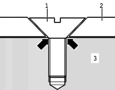
Pic. 2.152. Countersunk Screw Installation Diagram
After the second tightening, the screw point of the countersunk screws in the sensor gear is deformed so much that the screw heads lie on the crankshaft 3 and no longer press the sensor gear (pic. 2.152).
Installation of the sensor gear is possible only in one position, the holes are offset.
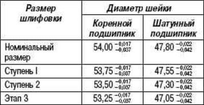
Crankshaft dimensions, mm
Main bearing marking
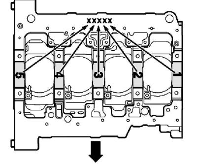
Pic. 2.153. Colored markings for bearing shells
The correct thickness of the upper bearing shells are installed in the cylinder block at the factory. Color markings are used to indicate the thickness of the bearing shells (pic. 2.153).
What thickness bearings should be used in a specific location, which is indicated on the lower seating surface of the cylinder block with a letter marking:
- G - yellow;
- B - blue;
- W - white.
Note: If the color marks are no longer visible, use a blue bearing shell.
Note: The lower main bearing shells are in principle supplied with «yellow» color marking.
Visitor comments