
Removing oil seals
Remove camshafts.
Vehicles with BLR, BLX, BVX and BVY engines
Note: To replace the valve stem seals for cylinders 3 and 4, the EGR valve must also be removed.
Continuation of assembly operations for all vehicles
Remove the roller arms and lay them on a clean surface. Roller levers do not change places.
Unscrew the spark plugs with a spark plug wrench.
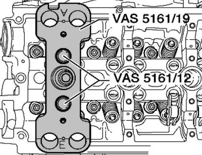
Pic. 2.117. Plate installation
Screw the guide plate with knurled bolts, as shown in Figure 2.117, to the cylinder head.
Bring the piston of the respective cylinder to «bottom dead center».
Screw the adapter into the spark plug socket and connect compressed air at a pressure of at least 6 bar.
Pic. 2.118. Branch of crackers
Pry off tight valve cotters with a mandrel and a plastic mallet (pic. 2.118).
Screw the attachment with suspension fork into the guide.
Insert the mounting cartridge into the guide plate.
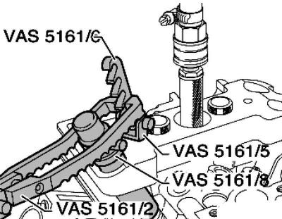
Pic. 2.119. Installation of devices for compression and drying
Hang the pressure fork to the fixture (pic. 2.119).

Pic. 2.120. Suspension of the pressure fork
Note: On the outlet side, the pressure fork should be suspended as shown in Figure 2.120.
Push the mounting cartridge down. At the same time, turn the knurled screw of the mounting cartridge to the right until the ends fit into the valve cotters.
Slightly turn the knurled bolt back and forth, due to this, the valve cotters are unclenched and the cartridge is captured.
Release the pressure fork.
Remove the mounting cartridge.
Pic. 2.121. Cap remover
Remove the valve stem seals with a puller (pic. 2.121).
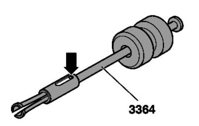
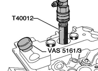
Pic. 2.122. Mandrel for pressing out
If the 3364 puller cannot be used due to lack of space, press out the pin with a drift and remove the nozzle (pic. 2.122).
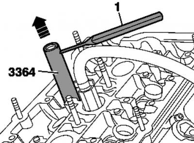
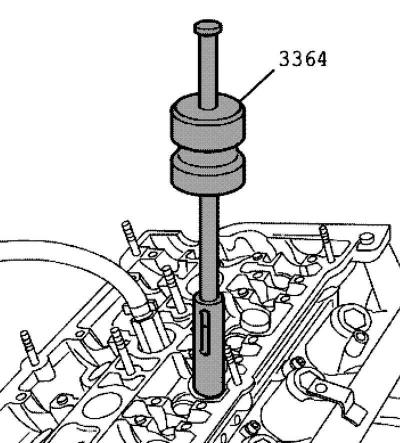
Pic. 2.123. Installing Seal 3364 on the Oil Seal
Push the bottom of the 3364 puller onto the oil seal (pic. 2.123).
Insert mandrel 1 into the hole at the bottom of the puller.
Pry out the mounting tool with a lever and thus remove the oil seal.
Installing valve stem seals
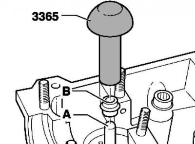
Pic. 2.124. Installing the oil seal
To avoid damage to new valve stem seals B, you need to put a plastic sleeve A on the valve stem (pic. 2.124).
Lubricate the lip of the valve stem seal B with engine oil, insert into the pressing tool and carefully press into the guide bushing.
Remove the plastic bushing A.
Insert the spring and valve spring cap.
Establish the adaptation for installation, as it is shown in drawing 2.119.
Note: After removing the valve cotters from the mounting cartridge, they must first be inserted into the mounting tool.
Press the mounting cartridge from above onto the mounting tool and, after installing, fix the valve cotters.
Press the mounting cartridge down with the pressure fork and turn the knurled bolt of the mounting cartridge back and forth, while pulling it up.
Unload the pressure fork with the knurled bolt extended.
Remove the valve pin mounting and dismounting tool.
Further installation and assembly is carried out in the reverse order of removal.
Visitor comments