



Note: When rotating the camshaft, the crankshaft must not be in the TDC position. There is a risk of damage to the valves and the piston crown.
Note: The engine should be warm to the touch.
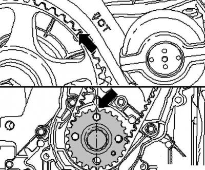
Fig. 2.102. TDC marks
Set the camshaft and crankshaft to the TDC mark (fig. 2.102).
Place the timing belt on the crankshaft pulley (observe the direction of travel).
Install the timing belt in the following order: tension roller, camshaft pulley, cooling system pump and, lastly, the guide roller.
Note: Make sure the tension roller is correctly positioned in the cylinder head.
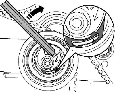
Fig. 2.103. Timing belt tension
Tighten the timing belt by turning the Allen bolt on the eccentric to the right (direction of the arrow), until the slot is positioned over the ledge (the timing belt is over-tensioned) (fig. 2.103).
Release the timing belt again.
Then tighten the timing belt until the slot and protrusion are aligned with each other.
Tighten the fastening nut to a torque of 25 Nm.
Turn the crankshaft two more revolutions in the direction of engine rotation until the engine is again at TDC. It is important that at the last 45° (1/8 turn) the rotation continued without interruption.
Check the timing belt tension again. The specified value The projection and the slot should be opposite each other.
Check the valve timing. The marks should match.
If the marks do not match, repeat the valve timing adjustment.
If the marks match, move the engine mount bracket to the installation position.
Note: Do not install the engine mount bracket mounting bolts yet. The engine mount bracket should sit "free" between the engine and the side member.
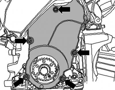
Fig. 2.104. Lower toothed belt guard
Install the lower timing belt guard (fig. 2.104).
Install the damper on the pulley with new bolts. Tightening torque 10 Nm + 90° further.
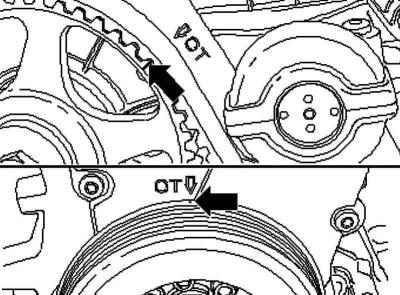
Fig. 2.105. Labels
Check the valve timing again. The marks should match (fig. 2.105).
Tighten both upper timing belt guard bolts.
Install the engine mount bracket to the cylinder block and tighten the top bolt.
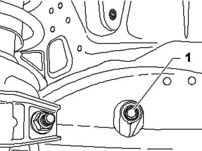
Fig. 2.106. Middle bolt
Lower the engine with a crossmember so that the middle bolt 1 can be tightened through the hole in the wheel arch (fig. 2.106).
Then insert the lower bolt and tighten all bolts to 45 Nm.
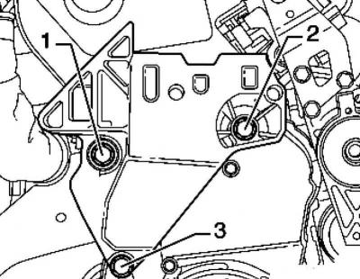
Fig. 2.107. Powertrain support bracket mounting bolts
Note: Pay attention to the difference in bolt length. Bolt 3 is approximately 25 mm shorter than bolts 1 and 2 (fig. 2.107).
Install the powertrain support in the engine area.
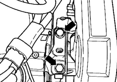
Fig. 2.96. Fastening the upper engine mount bracket
Screw in the power unit support bolts in the engine area and the engine support bracket, for which the support surfaces must be brought into contact using a crossbar (Fig. 2.96).
Straighten the engine mount as follows.
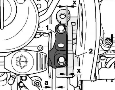
Fig. 2.100. Distance a between the engine support and the right side member
The distance A between the engine support bracket and the right side member must be at least 10 mm (fig. 2.100).
The cast edge on engine support bracket 2 must be parallel to foot 1.
Tighten the powertrain mount bolts at the engine section and the engine mount bracket.
Remove the crossbar.
Install the poly V-belt tensioner.
Install the poly V-belt.
Reconnect the fuel and ventilation lines. Make sure the quick-release couplings are securely fastened.
Install the expansion tank of the cooling system.
Reattach the pendulum support to the gearbox.
Install the front right fender liner.
Install soundproofing.
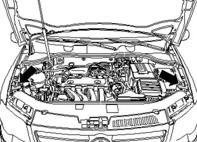
Fig. 2.108. Location of rubber bumpers
Install rubber hood bumpers (fig. 2.108).
Reinsert fuse #SD34 into the fuse box.
Install the engine cover.
Visitor comments