



Instructions: Adjustment of the timing belt is performed only on a cold engine, since the adjustment position of the tensioner changes depending on the temperature.
Remove the engine casing. Remove the fuel filter and additional fuel pump "V393". Disconnect the connector from the coolant temperature sensor at the radiator outlet "G83", unfasten the "arrow" clamps and remove the toothed belt casing. Remove the front right wheel arch liner. Remove the poly V-belt. Remove the torsional vibration damper.
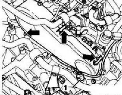
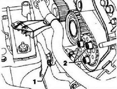
Remove the lower and middle toothed belt covers "arrows" and unscrew the cooling system tube fastening nut "1".
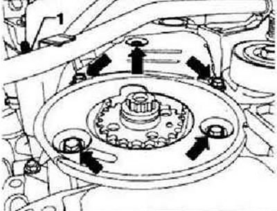
Bring the crankshaft to the TDC position of the first cylinder and lock the toothed pulley of the crankshaft using the "T10050" lock. To do this, insert the crankshaft stopper from the front part of the toothed belt pulley into its teeth. The toothed segment of the camshaft pulley should be facing upwards ("12 o'clock position").
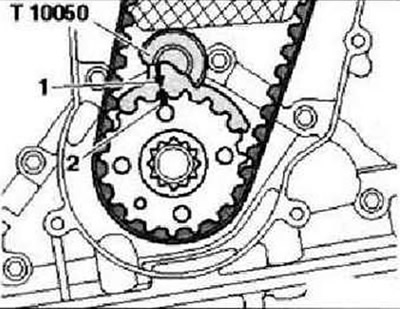
Instructions: Marks on the crankshaft toothed pulley "2" and the crankshaft lock "T10050" "1" must match. In this case, the pin of the crankshaft lock "T10050" must enter the hole of the cover.
Mark the direction of rotation of the toothed belt.
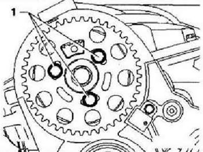
Loosen bolts "1" securing the camshaft pulley.
Loosen bolt "1" securing the cooling system tube, and then bolts "2" securing the fuel injection pump pulley.
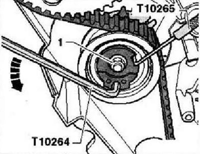
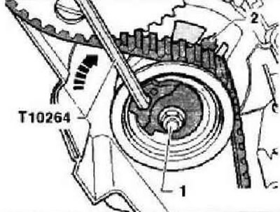
Loosen the tension roller fastening nut "1" and turn the tension roller eccentric with the socket wrench "T10264" counterclockwise "arrow" until the tension roller can be fixed with the lock "T10265".
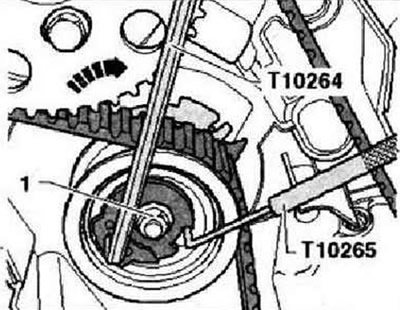
Now turn the tension roller eccentric clockwise "arrow" until it stops and manually tighten the fastening nut "1". Remove the toothed belt first from the guide roller, and then from the remaining toothed pulleys.
Installation
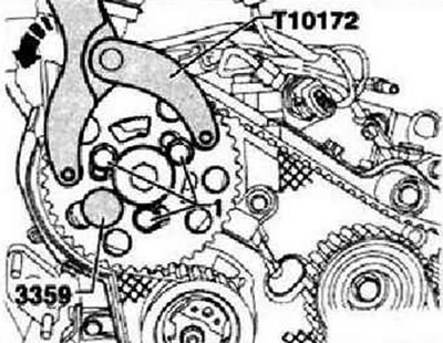
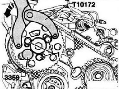
Instructions: Adjust the timing belt only on a cold engine, because the tensioner adjustment position changes depending on the temperature. If it is necessary to replace the tension roller, remove the support bracket. Replace the camshaft pulley and fuel injection pump mounting bolts. The tension roller must be retracted with the locking tool - T10265- and fixed in the extreme right position. The crankshaft is fixed with the locking tool "T10050". If necessary, turn the camshaft hub with the stop "T10172" and adapter -T10172/4- to a position where it can be locked. To do this, hand tighten at least one mounting bolt "1".
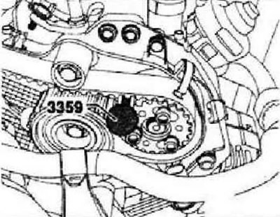
Fix the camshaft hub using the "3359" lock. To do this, insert the lock into the hole in the cylinder head through the free groove of the camshaft pulley. Loosen the hand-tightened bolts.
Instructions: If necessary, turn the fuel injection pump hub with a screwdriver to a position where it can be locked (the screwdriver should be supported on the bolt heads as shown in the figure).
Installing the fuel injection pump hub in the proper position
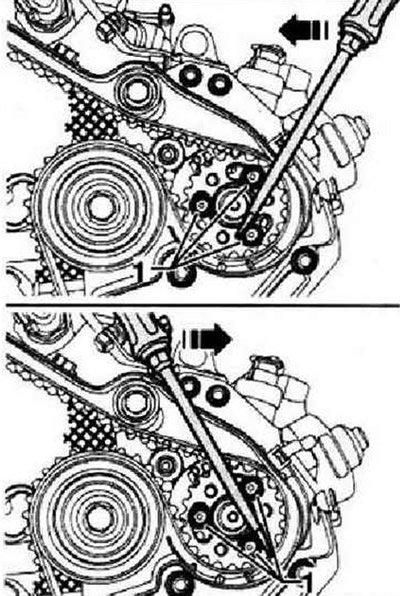
Fix the fuel injection pump hub using the locking device "3359". To do this, insert the locking device into the hole located on the side of the toothed pulley. Turn the camshaft pulley and the fuel injection pump pulley in the concentric grooves clockwise until they stop. Install the toothed belt on the crankshaft pulley, tension roller, camshaft pulley, coolant pump pulley and on the fuel injection pump pulley. Lastly, install the belt on the guide roller. Loosen the tension roller fastening nut and remove the locking device "T10265".
The article is posted on this website: www.VWMANUAL.ru
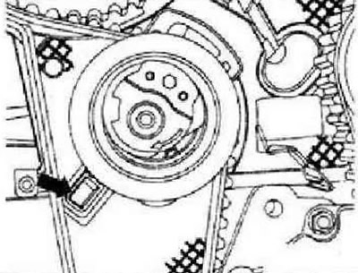
Instructions: Ensure proper position of the tension roller in the rear timing belt housing "arrow".
Carefully rotate the tension roller eccentric clockwise using the T10264 angle screwdriver until the indicator "2" is slightly above the middle of the hole in the base (is adjusted when prestressing is created). The fastening nut "1" should not rotate. Holding the tension roller in this position, tighten the fastening nut as follows: 20 Nm and turn it further by 45°.
Install the stop "T10172" as shown in the figure. Press the stop "T10172" in the direction of the arrow and hold the force on the camshaft pulley. Tighten the camshaft pulley mounting bolts "1" and the fuel injection pump pulley mounting bolts in this position, first by hand, then to a torque of 20 Nm. Remove the locks "3359" and the crankshaft pulley lock "T10050". Turn the crankshaft two revolutions in the direction of engine rotation and install it, slightly short of TDC of the first cylinder. Reinstall the lock "T10050" on the toothed pulley of the crankshaft.
Now turn the crankshaft in the direction of engine rotation until the crankshaft stop pin "arrow" from the rotational movement enters the sealing flange.
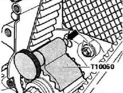
Instructions: Further testing is limited to simultaneous installation of the camshaft and crankshaft locks. Repeated fixation of the fuel injection pump hub is hardly possible. A slight misalignment of the "arrow" holes does not affect engine operation.
Check whether the camshaft hub can be fixed using the "3359" lock, whether the roller pointer is in the range between the middle of the hole in the base and the place 5 mm to the right of the hole in the base. If the camshaft hub cannot be fixed: pull the "T10050" crankshaft lock slightly towards you so that its pin comes out of the hole in the cover. Turn the crankshaft against the working direction of rotation so that the piston of the first cylinder is set in a position slightly before TDC. Then slowly turn the crankshaft in the working direction until it becomes possible to fix the camshaft hub. After fixing, loosen the camshaft toothed pulley fastening screws.
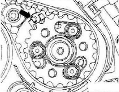
If the crankshaft lock pin "T10050" is located to the left of the cover hole
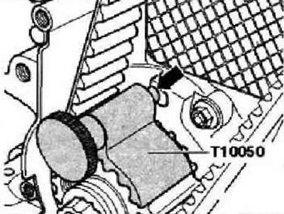
Turn the crankshaft in the working direction so that the crankshaft lock pin enters the cover hole during rotation. Tighten the camshaft toothed pulley mounting screws first by hand, then to a torque of 20 Nm.
If the crankshaft lock pin "T10050" is located to the right of the cover hole
Turn the crankshaft slightly against the working direction of rotation again. Now turn the crankshaft in the direction of engine rotation until the crankshaft locking pin from the rotating movement enters the sealing flange. Tighten the camshaft toothed pulley mounting screws first by hand, then with a torque of 20 Nm.
Continuation of the description of the works
Remove the camshaft pulley lock "3359" and the crankshaft pulley lock "T10050". Turn the crankshaft two revolutions in the direction of engine rotation and install it, slightly short of TDC of the first cylinder. Recheck the possibility of locking the crankshaft. If it is possible to lock the camshaft hub, tighten the mounting screws as follows. Camshaft pulley: turn it 45° further. Hold the pulley using the stop "T10172" and adapters -T10172/4-.
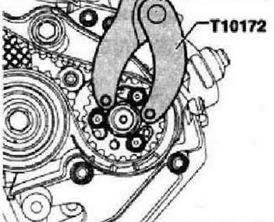
Fuel injection pump pulley: turn 90° further. Hold the pulley using the stop "T10172" and adapters -T10172/8-. Install the lower and middle toothed belt casing. Install the vibration damper/belt pulley: tightening torque: 10 Nm + turn 90° further.
Install the poly V-belt. Install the upper toothed belt guard. Further installation is carried out in the reverse order of removal. In this case, observe the following. Ensure proper fastening of the fuel hoses. Do not confuse the pressure and return lines (return line blue or with blue mark, pressure line white). Install the wheel arch liner. Install the sound-absorbing tray.
Visitor comments