



Caution: Take care not to damage the wire connections when removing the plug connectors, otherwise the entire wiring harness will have to be replaced. To remove the connectors, do not squeeze the pliers -3314- so hard that the mandrel is not damaged.
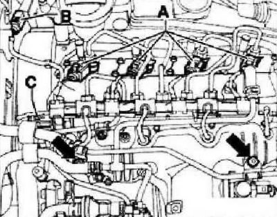
Fit the pliers -3314- with the groove -arrow A- on the collar of the mandrel -arrow B- and remove the connectors from the glow plugs.
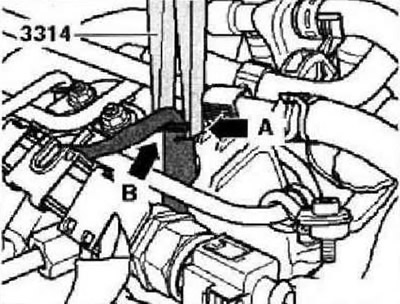
Remove connector carefully in -direction of arrow- from glow plug.
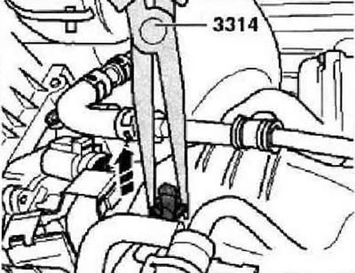
Unscrew nut securing fuel return line to intake manifold, open clamp -arrow- and detach line from rail.
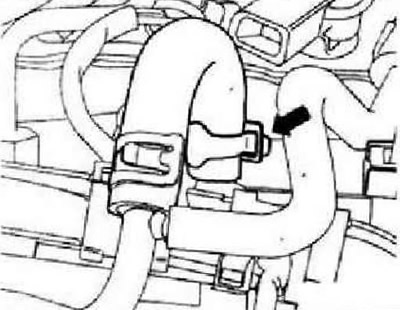
Disconnect the fuel return line fittings from the injectors. To do this, press the fitting down by the tabs and pull the middle part upwards to unlock it.
Instructions: It is necessary to monitor the maintenance of cleanliness, to prevent dirt from entering the removed fuel return lines and injector connectors.
Remove the fuel return line assembly and lay it in front of the intake manifold.
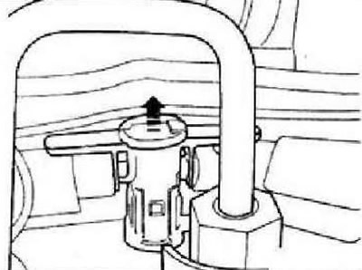
Unplug connector for turbocharger guide vane position sender -G581- -arrow- at turbocharger and remove cable from retainers.
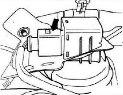
Unplug connector from fuel pressure regulator -M276- -arrow-. Remove the cable guide from the rail, Disconnect the vacuum line from the valve cover. Remove other vacuum pipes from bracket on valve cover. Remove upper toothed belt cover. Remove the crankcase breather pipe between the valve cover and air intake hose. To do this, press and compress the fasteners of the quick-release fitting. Remove high pressure pipe between injection pump and rail. Remove high pressure lines between rail and injectors.
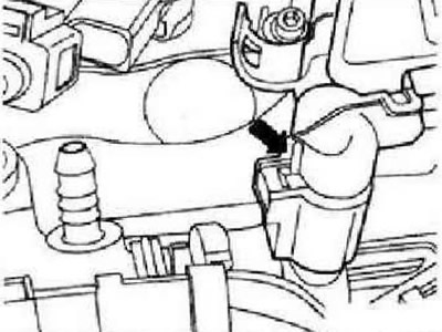
Remove bolts -arrows- and remove ramp. Remove nozzles. Loosen the valve cover screws and remove it.
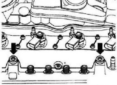
Installation in reverse order. In doing so, observe the following.
Note: Bolt seals must be replaced if damaged.
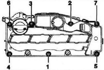
Tighten by hand in the sequence 1...7 the valve cover bolts. Tighten bolts in sequence 1...7 to 10 Nm. Check that the valve cover and toothed belt guard are properly connected.
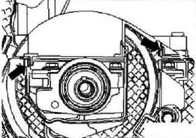
Instruction: For clarity, the camshaft pulley is not shown in the figure.
To install correctly, use a screwdriver to press the belt guard at the mounting points -arrows- towards the valve cover. The latches should click into place with a distinct click. Check for clearance between hub and toothed belt guard. Install high pressure lines.
Visitor comments