
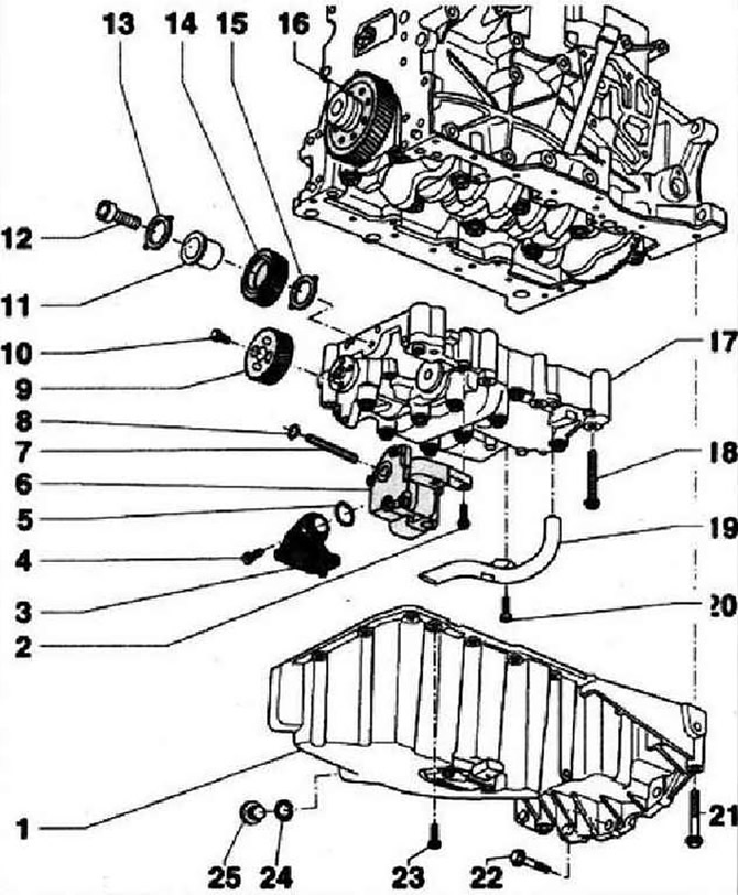
- 1 - Oil pan
- 2 - 10 Nm
- 3 - Suction pipe, if dirty, clean the mesh
- 4 - 10 Nm
- 5 - O-ring, replace
- 6 - Oil pump, before installation, check the presence of both centering sleeves that determine the relative position of the balancing shaft block and the cylinder block
- 7 - Oil pump drive shaft
- 8 - Retaining ring, must rest against the base of the groove, replace a damaged or stretched ring
- 9 - Cylindrical gear balancer shaft
- 10 - 20 Nm and tighten by 90°, replace
- 11 - Idle gear hub, replace
- 12 - 90 Nm and tighten by 90°, replace
- 13 - Thrust washer for idler gear, replace, observe installation position
- 14 - Intermediate gear, replace. To ensure correct backlash in the gearing, a special coating is applied to the new gear wheel, after the break-in in the gearing, the proper backlash is formed. When installing the idler gear, properly install the thrust washer. Mounting position: part number must be visible
- 15 - Thrust washer for idler gear, replace, observe installation position, fix to housing with grease if necessary before installing gear
- 16 - Crankshaft drive sprocket, replace if worn
- 17 - Block of balancing shafts, before installation, check the presence of both centering sleeves that determine the relative position of the block of balancing shafts and the cylinder block
- 18 - M7 = 13 Nm, then tighten by 90°; M8 = 20 Nm, then tighten by 90°, replace, follow the tightening sequence: install a new balancer shaft assembly
- 19 - Oil receiver tube
- 20 - 10 Nm
- 21 - 40 Nm
- 22 - 45 Nm
- 23 - 15 Nm, tighten in stages crosswise
- 24 - O-ring, integral, rolled into the drain plug
- 25 - Oil drain plug - 30 Nm, with O-ring, replace
Piston cooling nozzle and pressure reducing valve
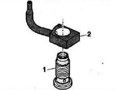
- 1 - Screw with pressure reducing valve - 27 Nm
- 2 - Piston cooling nozzle
Visitor comments