



Removal
Note: For further operations, the ground wire must be disconnected from the battery. Therefore, it is necessary to first check whether the car radio with coding is installed.
Note: The engine is removed together with the gearbox downwards.
Note: After installing the engine, it is necessary to reinstall all cable clamps in the same places that were removed or cut during its dismantling.
Caution: When carrying out any installation work, particularly in the engine compartment due to the tight layout, the following must be taken into account.
Attention: Highways of all types (for example fuel, hydraulic, activated carbon canister, cooling systems, air conditioning circuits, brake lines, vacuum hoses), and also the electrical wires must be laid as they were originally laid.
Caution: To avoid damage, ensure sufficient clearance to all moving and hot parts.
Disconnect the ground wire from the battery with the ignition off.
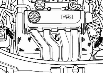
Fig. 2.82. Engine casing
Remove the engine cover, if present (Fig. 2.82).
Disconnect hose 1 and connector from intake air temperature sensor 2 on the air filter housing.
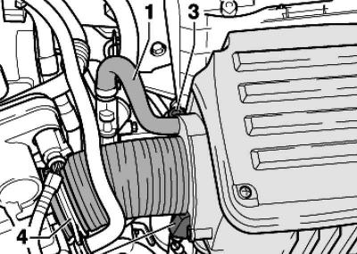
Fig. 2.83. Air filter housing with air hose
Unscrew bolt 3 and remove the air filter housing with air hose 4 (Fig. 2.83).
Remove the battery and the battery holder frame.
Remove the wiper arms, water drain box housing and water drain box on the front wall.
Disconnect the engine wiring harness connector at the engine control module.
Remove the wiper arms and the water drain box cover.
Disconnect the engine wiring harness connector at the engine control module.
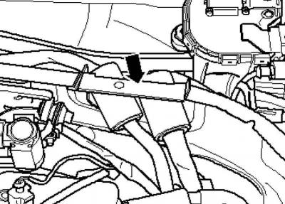
Fig. 2.84. Engine wiring harness entry holder
Unlock the engine wiring harness entry and pull it upwards (Fig. 2.84).
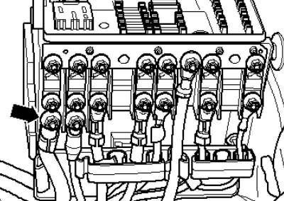
Fig. 2.85. Fastening the generator cable to the fuse box
Unscrew the generator cable from the fuse box (Fig. 2.85).
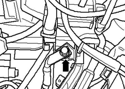
Fig. 2.86. Fastening the ground cable
Unscrew the ground cable from the side member (Fig. 2.86).
Open the cable clamps on the side member.
Disconnect the plug connections of the engine wiring harness from the body and place the wiring harness on the engine.
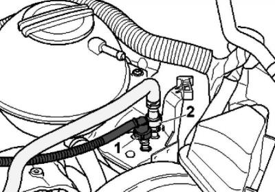
Fig. 2.87. Pipeline and fuel line
Disconnect ventilation line 1 and fuel line 2. To do this, press on the clamps (Fig. 2.87).
Remove the noise insulation screen.
Place the radiator frame in the service position.
Drain the coolant.
Remove the front left fender liner.
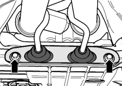
Fig. 2.88. Exhaust system holder
Unscrew the exhaust system holder (Fig. 2.88).
Note: On vehicles with engine letter designations BLX and BVX, the exhaust system bracket is removed together with the lambda probe cable box behind the catalytic converter.
Front wheel drive cars
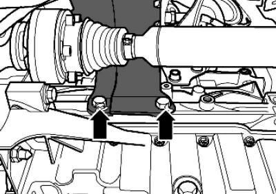
Fig. 2.89. Fastening the heat shield
Remove the heat shield of the right PTO shaft (Fig. 2.89).
Continuation of installation operations for all vehicles
Remove the right drive shaft and unscrew the left drive shaft from the transmission.
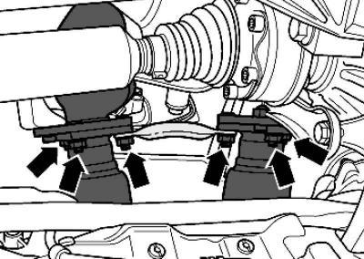
Fig. 2.90. Fastening the inlet pipe
Unscrew the nuts securing the inlet pipe to the exhaust manifold and disconnect it from the exhaust manifold (Fig. 2.90).
Note: The detachable elements in the intake pipe must not be bent more than 10°.
Cars with engine letter designations BLX, BVX
Remove the catalytic converter with NO memory.
Remove the front propeller shaft pipe.
Continuation of installation operations for all vehicles
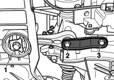
Fig. 2.91. Swing support bracket
Unscrew bolts 1–3 and remove the rocker support (Fig. 2.91).
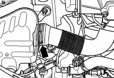
Fig. 2.92. Air duct hose
Disconnect the air duct hose at the bottom of the expansion tank and remove it (Fig. 2.92).
Remove the terminals, disconnect and release all remaining existing electrical wires from the engine/transmission.
Disconnect all connecting, vacuum, inlet, coolant supply and return hoses from the engine.
Note: To avoid damage to the condenser and the air conditioning system circuit lines and hoses, ensure that the lines and hoses are routed without tension, kinks or bends.
Note: To be able to remove and install the engine also without opening the coolant circulation circuit.
Remove the poly V-belt.
Unscrew the air conditioning compressor from the bracket.
Secure the air conditioning compressor to the locking bracket so that there is no load on the refrigerant lines/hoses.
Cars with manual transmission
Remove the gear shift drive from the gearbox.
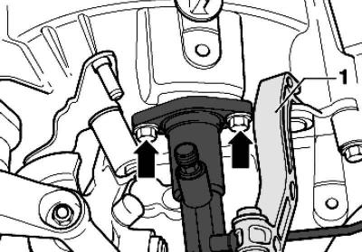
Fig. 2.93. Clutch tensioner and slave cylinder
Remove stretcher 1 (Fig. 2.93).
Remove the clutch slave cylinder and set it aside, do not open the lines.
Caution: Do not press the clutch pedal after removing the slave cylinder. The slave cylinder may be damaged.
Cars with automatic transmission
Remove the selector cable from the gearbox.
Continuation of installation operations for all vehicles
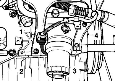
Fig. 2.94. Connecting plug
Remove connecting plug 1 from the mount (Fig. 2.94).
Remove bolts 2–4.
Install the engine stand into the engine and transmission mount.
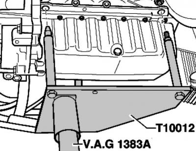
Fig. 2.95. Installing the rack
Place the engine stand, as shown in Figure 2.95, on the engine and tighten it to the cylinder block with a tightening torque of approximately 20 Nm.
Screw the engine strut through the intake manifold support with a M10x25 mounting bolt with a torque of 20 Nm to the cylinder block.
Raise the engine and transmission slightly using an engine and transmission stand.
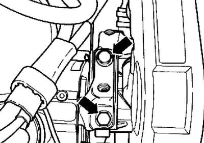
Fig. 2.96. Fastening the upper engine mount bracket
Unscrew the power unit suspension from the upper engine support (Fig. 2.96).
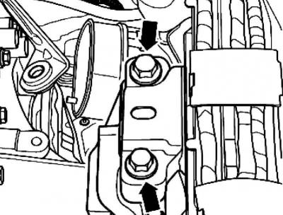
Fig. 2.97. Fastening the gearbox support bracket
Unscrew the power unit suspension from the gearbox support (Fig. 2.97).
Note: Use a stepladder to loosen the mounting bolts.
The engine and gearbox must be lowered carefully to avoid damage to the body.
Carefully lower the engine and gearbox down.
Mounting the engine on a mounting stand
To carry out installation work, the engine must be secured to the engine and gearbox retainer.
Unbolt the gearbox from the engine.
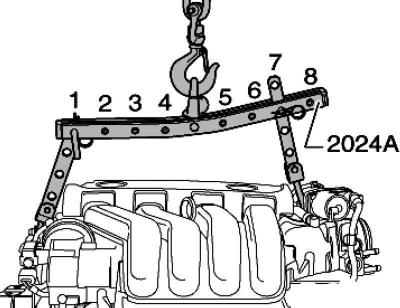
Fig. 2.98. Hanging device
Hang the lifting device as follows and lift it with a crane from the engine and gearbox stand (Fig. 2.98).
From the pulley side, the 4th hole of the guide is in position 1
From the flywheel side, the 3rd hole of the guide is in position 7
Caution: To avoid damage to the engine and vehicle, use special safety pins in the hooks and locking pins.
Holes 1-4 of the carrier bar point towards the belt pulleys.
The number of holes in the planks is counted from the hook.
Secure the engine to the engine and transmission mount.
Engine installation
Installation is carried out in the reverse order, taking into account the following.
Insert new engine and transmission alignment bushings into the cylinder block.
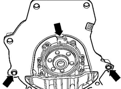
Fig. 2.99. Intermediate plate
Hang the intermediate plate on the sealing flange and place it on the fitted bushings (Fig. 2.99).
Cars with manual transmission
Lightly lubricate the input shaft teeth with grease.
Check and install the clutch and clutch drive.
Continuation of installation operations for all vehicles
When installing the power unit (engine with gearbox) make sure there is sufficient clearance to the subframe and radiator.
Align the engine mount as follows:
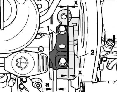
Fig. 2.100. Distance a between the engine support and the right side member
The distance between the engine support and the right side member a must be at least 10 mm (fig. 2.100).
The cast edge in engine support 2 must be positioned parallel to bracket 1.
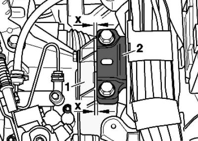
Fig. 2.101. Checking the parallelism of the edges of the bracket and the gearbox console
On the gearbox side, pay attention to the parallelism of the edges of bracket 2 and gearbox console 1 (fig. 2.101).
Install the rocker support.
Install the right drive shaft and bolt the left drive shaft to the gearbox.
All-wheel drive vehicles
Install the front propeller shaft pipe.
Cars with letter designation BLR, BVY
Screw on the catalytic converter inlet pipe.
Cars with engine letter designation BLX, BVX
Install a catalyst with NOx memory.
Cars with engine letter designation BLY, BVZ
Screw on the catalytic converter inlet pipe.
Cars with manual transmission
Install the shift drive and adjust if necessary.
Install the hydraulic clutch slave cylinder.
Cars with automatic transmission
Install the selector drive cable and adjust it if necessary.
Continuation of installation operations for all vehicles
Install the air conditioning compressor.
Install the poly V-belt.
Install a noise insulation screen.
Connect the connector to the engine control unit.
Install the battery and battery holder frame.
Fill with coolant.
Take it for a test drive.
Then test the vehicle's systems and troubleshoot any problems that may arise.
Note: After clearing the fault memory, you must generate an OBD code.
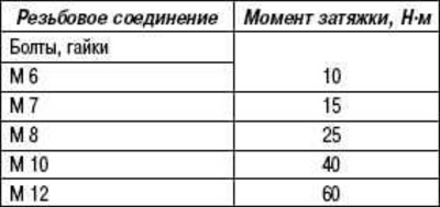
Tightening torques
Visitor comments