



Caution: When carrying out any installation work, particularly in the engine compartment due to the tight layout, the following must be taken into account. Lines of all types (for example, fuel, hydraulic, activated carbon canister, cooling systems, refrigerant circuits, brake system lines and hoses, vacuum), and also the electrical wires must be laid as they were laid initially. To avoid damage, ensure that there is sufficient free space to reach all moving and hot parts.
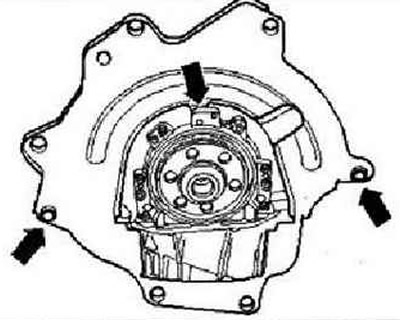
Check the clutch release bearing for wear and replace if necessary. Lightly lubricate the clutch release bearing, bearing guide sleeve and input shaft teeth with G OOO 100 grease. Check the cylinder block for fitted bushings for centering the engine and gearbox and install them if necessary. Hang the intermediate plate on the flange and place it on the fitted bushings "arrows".
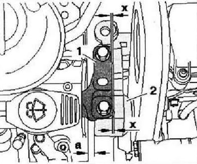
Align the engine mount as follows. The distance "a" between the engine mount and the right side member must be at least 10 mm. The cast edge in the engine mount "2" must be parallel to the bracket "1".
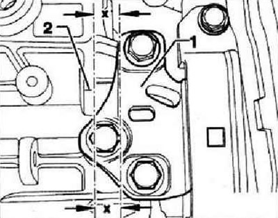
On the gearbox side, pay attention to the parallelism of the edges of bracket 1 and gearbox console "2".
Install the gearbox bracket for the angular gearbox. Install the exhaust pipe.
Instructions: First tighten the mounting nuts by hand.
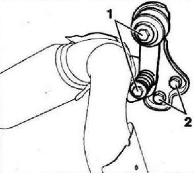
Install the exhaust pipe support and tighten the mounting bolts "1" and "2" to 25 Nm. Install the subframe.
The information is posted on this website www.VWmanual.ru
Install the propeller shaft. Install the drive shafts. Install the gearshift drive. Connect hose "1" of the hydraulic clutch slave cylinder. Install the lower support of the power unit. Install the air conditioning compressor. Install the poly V-belt. Electrical connections and wiring. Fill with coolant. Install the air filter. Install the battery and battery holder. Connect the battery. Press the engine casing at points "1" - in the direction of the arrow - downwards until it is secured at these points by latches. Place the vacuum line on the connecting nipple "arrow". Connect the tester -VAS 5051 B-. Erase previous readings and adapt the regulating valve control unit and the throttle valve control unit. Carry out diagnostics of the vehicle systems. Complete diagnostics of the vehicle systems so that errors that may have been recorded during installation are automatically deleted from the fault memory. Carry out a test drive. After this, repeat the diagnostics of the vehicle systems and, if necessary, eliminate any errors that have arisen.
Tightening torques
| M6 | 10 Nm |
| M8 | 20 Nm |
| M10 | 45 Nm |
| M12 | 60 Nm |
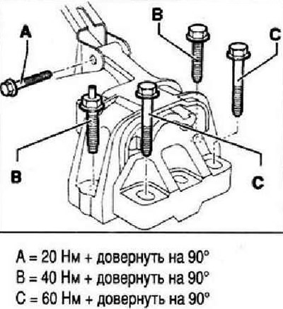
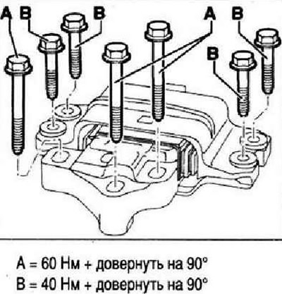
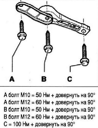
Powertrain suspension - tightening torques
Instructions: The component support mounting bolts are flexible bolts and must be replaced.
Powertrain suspension, engine
Powertrain suspension, gearbox
Lower support of the power unit
Visitor comments