



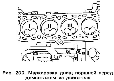
Mark each connecting rod-piston pair according to the cylinder number from which they will be removed. This is best done with paint, applying the cylinder numbers to the piston crowns (figure 200). Supplement the numbers with an arrow pointing toward the front of the engine. The orientation of the parts can also be determined by the recesses for the valves.
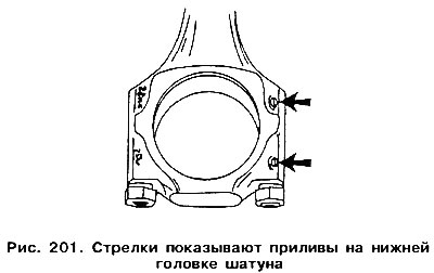
When removing the piston with the connecting rod, you need to remember the position of the connecting rod cap. Immediately after removal, it is recommended to mark both the cap and the lower head of the connecting rod, applying the cylinder number on one side (see figure 65). The cap and lower connecting rod head are factory fitted with bosses (figure 201), which after assembly must be aligned on the intermediate shaft side.
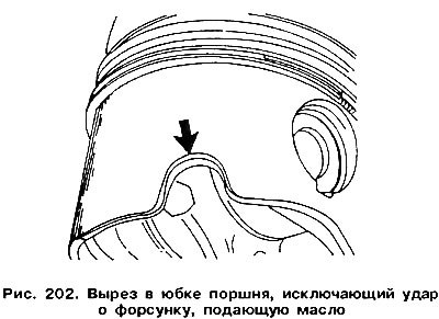
Turbocharged engine pistons have a cutout on one side of the skirt. This prevents the piston from hitting the injector for supplying oil at BDC. When installing the piston, the cutout must be on the injector side (figure 202).
Either deformable connecting rod bolts with a thread length of 25 mm or non-deformable connecting rod bolts with a thread length of 15 mm may be used. Deformable connecting rod bolts cannot be reused when assembling connecting rod caps. Only deformable connecting rod bolts are used in turbocharged engines.
In engines with hydraulic tappets, pistons of groups II and III have a chamfer of 15°. If new pistons are installed, they must have the specified chamfers. Mark the liners of each connecting rod. To distinguish the upper and lower liners, you can mark them with paint on the convex part. After removing the connecting rod caps and liners, remove the pistons with the connecting rods upwards from the cylinder block. If necessary, remove the upper flange from the surface of the cylinder mirror. Remove the retaining rings and remove the piston pin. The recess next to the hole for the pin allows you to use a sharp object (an awl) to pry up the retaining ring, as shown in figure 68.
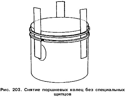
Remove the piston rings one by one from the pistons using piston ring pliers (see figure 69). If the rings are to be used again, they must be marked. If there are no special pliers, steel strips can be used, which are placed under the rings around the circumference at 120°. One of the steel strips is placed under the ring locks so as not to damage the cylinder mirror (figure 203).
Visitor comments