



 |
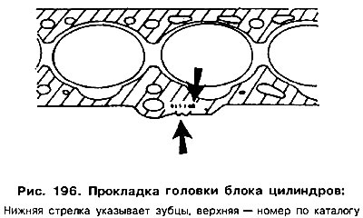 |
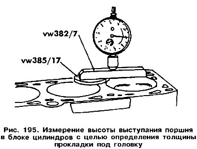
Data for engine without hydraulic tappets:
| protrusion height | number of risks |
| 0.67-0.80 mm | 1 |
| 0.81-0.90 mm | 2 |
| 0.91-1.02 mm | 3 |
Data for engine with hydraulic valve lifters:
| protrusion height | number of risks |
| 0.66-0.86 mm | 1 |
| 0.87-0.90 mm | 2 |
| 0.91-1.02 mm | 3 |
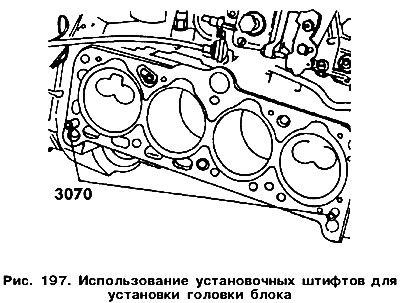
To install the cylinder head correctly, it is necessary to use special installation pins that are screwed into the cylinder block from the intake manifold side in the area shown in Figure 197, for which: Clean the mating surfaces of the head and cylinder block.
Tighten all bolts in the specified sequence to a torque of 60 Nm (second stage of tightening).
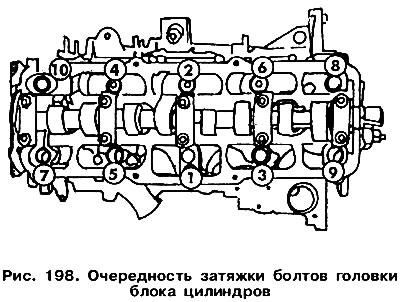
Replace the torque wrench with a regular one and tighten each bolt exactly half a turn in the order specified. Tightening twice by a quarter turn (2x90°) is possible.
Start the engine and let it warm up. Tighten the bolts in the order shown exactly 1/4 turn with a smooth, continuous motion.
After a run of about 1000 km, the bolts should be tightened in the specified order with a smooth, continuous movement by another 1/4 turn. The engine can be cold or warm.
All other actions are performed in the reverse order of disassembly.
Visitor comments