



Insert the valve into the sleeve and press firmly against the seat.
Measure the distance "A" between the end of the valve and the top edge of the head (see figure 52).
Determine the permissible size of the working chamfer by subtracting from the measured value "A" the permissible minimum distance of the end of the rod from the edge of the cylinder head, which is 35.8 mm for the intake valve and 36.1 mm for the exhaust valve.
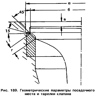
Check the seats for wear. Minor wear can be corrected with a 45° milling cutter. If the working chamfer has deep pits, the seats must be machined again. The seats are milled when the guide bushings are replaced. First, the working chamfer itself is machined with a 45° milling cutter, and then the upper part with a 15° milling cutter so that the working zone width is 2.0 mm for the inlet valves and 2.4 mm for the exhaust valves.
The treatment is finished when the required width of the working chamfer is reached. It is recommended to check that the working chamfer is not too deep in the head. To do this, insert the valve into the seat and measure the dimension "b" using a depth gauge (see figure 189). If it exceeds 1.5 mm, the seat is too deep and the head must be replaced.
Attention! If the engine is equipped with a head with a camshaft after restoration at the manufacturer, then the valve clearances do not need to be adjusted (in vehicles manufactured since 1986.), since the head is equipped with hydraulic tappets. It is recommended to thoroughly lubricate the contact surfaces of the tappets with the camshaft cams before installing the head. The plastic caps that prevent the valve from falling out can only be removed after installing the head.
After machining the seat, the working chamfers of the seat and valve must be lapped. To do this, cover the surface chamfers with lapping paste and insert the valve into the hole. Attach the device to the valve and, pressing it against the seat, turn the valve in both directions (see figure 53). After that, remove the paste and clean all the parts. Check the chamfers of the valve plate and seat. On both surfaces, a solid matte ring of a width corresponding to the width of the working chamfer should be visible. On the working surface of the valve plate, make several marks with a pencil approximately every 1 mm, insert the valve into the sleeve and sink the plate into the seat. Pressing hard, turn the valve by 900. Remove the valve and check whether the pencil marks have disappeared from the working chamfer. If the belt width is within the permissible limits, you can proceed to install the cylinder head. Otherwise, continue grinding or install a restored cylinder head.
(View the original article on the resource vwmanual.ru)
Visitor comments