



The camshaft, located in the cylinder head, has five bearing journals. To gain access to the valve springs and tappets, it is necessary to remove the camshaft. During this operation, special recommendations should be followed to avoid deformation of the shaft under the influence of the valve springs. Each engine modification corresponds to a specific camshaft design, so when replacing it, you should carefully check the part number in the catalog.
No periodic adjustment of valve clearances is required. In cars manufactured before the end of 1985, whose engines are not equipped with hydraulic tappets, valve clearances change insignificantly over a long period of operation, their value depends entirely on the degree of wear of the tappets, valves and cams, which in itself suggests the need to complete the repair. The procedure for adjusting valve clearances is given in Section 4 for gasoline engines with working volumes of 1.6 and 1.8 liters. In engines installed after 1986, hydraulic tappets with automatic clearance correction are used.
Valve springs, valve seats and valve stem seals are difficult to access because they are located deep in the cylinder head. The following recommendations are written assuming that users have the appropriate tools and will follow the instructions exactly. When disassembling the valves, attention should be paid to how individual components such as tappets, cotters, upper and lower spring retainers, outer and inner valve springs and adjusting washers were installed.
It should be recalled that in engines installed before 1986, it is possible to adjust the valve clearances without removing the camshaft. To do this, you need a special device that allows you to remove the adjusting washers.
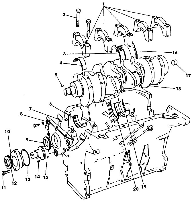
Figure 183. Cylinder block. Central liners No.3 and liners No.5 in serial engines are supplemented with thrust half rings: 1 - main bearing caps; 2 - main bearing cap bolt (65 Nm); 3 - lower main bearing shell No.3; 4 - liner without oil groove; 5 - key; 6 - liner with oil groove; 7 - gasket; 8 - Front oil seal cover 9 - Oil seal; 10 - gland flange; 11 - bolt (23 Nm); 12 - intermediate shaft seal; 13 - O-ring round section; 14 - key; 15 - intermediate shaft; 16 - lower thrust half ring; 17 - bearing (needle); 18 - crankshaft; 19 - upper main bearing shell No.3; 20 - upper thrust half ring
Visitor comments