
Remove the vacuum pump, exhaust manifold, coolant pump and other accessories from the engine.
Unscrew the four bolts securing the V-belt pulley to the crankshaft and remove it, as well as the damper behind it. Remove the upper part of the toothed belt guard. It is attached with one bolt to the top and two to the front end of the cylinder block. Remove the lower part of the toothed belt guard. Remove toothed belt (see here) and belt tensioner.
Having unscrewed the central bolt, remove the toothed pulley from the crankshaft. The crankshaft must be fixed by blocking the flywheel. Remove the oil dipstick.
Remove the valve cover and remove the gasket. Remove the cylinder head. Turn off bolts of fastening of a head of the block in regular intervals, in sequence, return shown in fig. 182. To unscrew the bolts, a special socket wrench is required, without which it is possible to damage the bolt heads, which will make it impossible to unscrew them. These bolts cannot be reused.
Turn the engine over and remove the oil pan.
Remove the gasket.
Unscrew the oil pump from the cylinder block wall and remove it.
Be sure to mark the connecting rod caps with paint in accordance with the serial numbers of the cylinders and remove.
When removing the covers, the two connecting rods must be at BDC. Push the connecting rods together with the pistons from the cylinders upwards. The connecting rod caps, together with the liners, must be screwed into place immediately.
From a forward wall of the engine remove the holder of a forward epiploon and remove a lining. The gland can be knocked out of the holder. Remove clutch and flywheel. The flywheel must be locked. Remove the drive disk from the crankshaft (in case of automatic transmission).
Remove the crankshaft rear oil seal holder and knock out the oil seal.
Remove the crankshaft. Bearing caps must be numbered (No. 1 on the pulley side, No. 5 on the flywheel side).
Remove the toothed pulley from the intermediate shaft.
Loosen the bolts securing the intermediate shaft flange and remove the flange, under which there is an O-ring. Remove the shaft from the engine block.
The details which are subject to dismantle from the block of cylinders are shown on fig. 183.
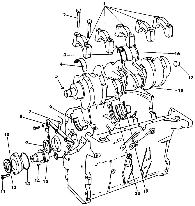
Pic. 183. Cylinder block. Central liners No. 3 and liners No. 5 in serial engines are supplemented with thrust half rings: 1 - main bearing caps; 2 - main bearing cap bolt (65 Nm); 3 - lower shell of the main bearing N2 3 4 - shell without oil groove; 5 - key; 6 - liner with an oil groove; 7 - gasket; 8 - front oil seal cover 9 - oil seal; 10 - stuffing box flange; 11 - bolt (23 Nm); 12 - intermediate shaft seal; 13 - O-ring; 14 - key; 15 - intermediate shaft; 16 - lower thrust half ring; 17 - bearing (needle); 18 - crankshaft; 19 - the upper loose leaf of the main bearing N2 3; 20 - upper thrust half ring
Visitor comments