
English Русский
Български
Беларускі
Український
Српски
Hrvatski
Română
Polski
Slovenský
Magyar
  |  Articles  |  Sitemap  |  Contacts  |    |
Car maintenance Ford Car maintenance Hyundai Car maintenance Chevrolet Car maintenance BMW Car maintenance Audi Car maintenance Opel Car maintenance AvtoVAZ
VWmanual.ru


Main   Passat   Golf   Polo   Touareg   Tiguan   Sharan   Transporter   Others  
Golf 1 (1974-1984, diesel) Golf 1 (1974-1984, petrol) Golf 2 (1984-1993, petrol) Golf 2 (1984-1993) Golf 3 (1991-1997) Golf 4 (1997-2004) Golf 5 (2003-2008)

Installation of connecting rod and piston group (VW Golf 2)

  • Main
  • Golf
  • Golf 2
  • Diesel engines
  • Engine repair
  • Installation of connecting rod and piston group
            0


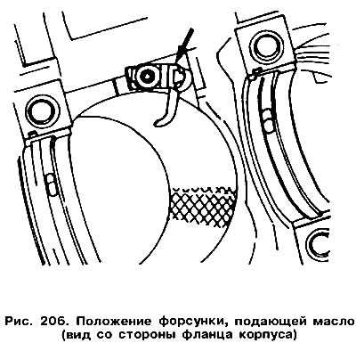
If the oil jets used to cool the pistons have been removed from a turbocharged engine, they must be reinstalled in their original locations (figure 206). Tighten the injector mounting bolts to a torque of 10 Nm.

If the oil jets used to cool the pistons have been removed from a turbocharged engine, they must be…


Generously lubricate the surface of the cylinder mirrors with clean engine oil.

Install the connecting rods with pistons in the cylinder block according to the cylinder numbering. The lugs on the lower head and the connecting rod cover must be installed on the intermediate shaft side.

The arrows on the piston crowns must point towards the front of the engine.

Set piston ring locks at 120° figure 199 shows how the ring locks should be installed relative to the piston pin axis.

Place the piston rings in the cage as shown figure 78, and sink the rings into the grooves.

Before inserting the pistons into the cylinders, check again whether the piston pin is locked on both sides. It may happen that after installing one locking ring, you forgot to install the second one. Turn the crankshaft so that the two cranks are at BDC.

Insert the connecting rod into the cylinder bore from above. Before doing this, wrap the lower head of the connecting rod with polyethylene to avoid damaging the cylinder bore. The cylinder block should be placed on its side to facilitate installation of the connecting rod bearing caps. The connecting rod bearing shell should already be installed in the lower head of the connecting rod, so that the projection of the bearing shell is aligned with the groove in the connecting rod head.


Insert the piston into the cylinder so that the rings enter the cylinder and the lower head is installed on the crankshaft journal.

Place the second part of the liner into the connecting rod bearing cap and lubricate it well with engine oil. Place the cap on the connecting rod bolts and tap it lightly, having first removed the protective material from the bolts. Once again, make sure that the lugs on the lower head and the connecting rod cap match (see figure 201).

Lubricate the areas where the nuts meet the connecting rod cap.

Tightening of connecting rod bolts is carried out depending on the types of bolts installed:
  • if old design bolts are used, as shown on the right side in Figure 207, the new nuts are tightened to a torque of 50 Nm;
  • if the new design bolts shown on the left side in Figure 207 are used, the new nuts are tightened to a torque of 30 Nm and then tightened another half turn.
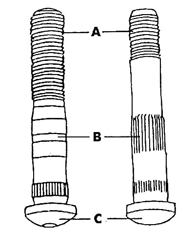
Figure 207. Connecting rod bearing cap mounting bolts (on the left is the new deformable one, and…

Figure 207. Connecting rod bearing cap mounting bolts (on the left is the new deformable one, and on the right is the old regular one): A - new bolt M8x1.25 mm or old bolt M9x1.25; B - smooth surface (new bolt) or with a toothed knurling (old bolt); C - conical head (new bolt) or round (old bolt)


After installing each connecting rod, rotate the crankshaft several times to check if anything is interfering with its rotation.

Recheck the orientation of all connecting rods and the correct installation of pistons. In turbocharged engines, also check whether the cutouts in the piston skirts are on the side of the injectors that inject oil.

Measure the clearance between the side surface of the connecting rod and the bearing surface of the crankpin (see figure 79), which is equal to the value of the axial clearance of the shaft and should not exceed 0.37 mm.

If the clearance is greater than specified, replace the connecting rods. Put short pieces of rubber or plastic tubes on the connecting rod bolts to prevent possible damage to the cylinder bore surface.

This article is available at russian, bulgarian, belarusian, ukrainian, serbian, croatian, romanian, polish, slovak, hungarian
The text has been checked: Kolesnikov Artem

Share information:

Previous articles
Assembly of the connecting rod and piston group
Checking the connecting rod and piston group parts
Removal connecting rod and piston group parts from the cylinder block
Pistons and connecting rods — design description
Installing the cylinder head
Cylinder head assembly
Next articles
Measuring the axial clearance of the crankshaft
Removal the crankshaft
Replacing crankshaft seals
Checking the crankshaft
Installing the crankshaft
Cylinder Block — Check


Similar articles from other manuals for VW cars:
Connecting rod and piston group Passat B4 (1988-1996)
Connecting rod and piston group Polo 3 (1995-2003)
Disabling and connecting airbags Touareg 1 (2002-2006)
Connecting brake pipes from the master cylinder to the hydraulic… Tiguan 1 (2007-2015)
Connecting rod and piston group — design description Sharan 1 (1995-2000)
Connecting the remote control Transporter T4 (1990-2003)
Connecting rod and piston group Caddy 3 (2003-2010)
Link to this page in different formats


Visitor comments


No comments yet


How much will 24 + 32 =


Golf 5 
  • General information
  • User manual
  • Maintenance
  • Troubleshooting
  • Power unit
  • Engine repair
  • Cooling and ventilation system
  • Fuel system
  • Ignition system
  • Transmission
  • Clutch
  • Mechanical gearbox
  • Automatic gearbox
  • Chassis
  • Brake system
  • Car suspension
  • Steering
  • Body
  • Interior (internal elements)
  • Exterior (external elements)
  • Doors and covers
  • Electrical equipment
  • Power devices
  • Washers and wipers
  • Lighting and appliances
  • Electrical circuits
Golf 4 
  • General information
  • User manual
  • Weekly checks
  • Maintenance
  • Power unit
  • Petrol engines
  • Diesel engines
  • Cooling system
  • Fuel system (petrol)
  • Control system (petrol)
  • Fuel system (diesel)
  • Exhaust system
  • Transmission
  • Clutch
  • Car gearbox
  • Drive shafts
  • Chassis
  • Car suspension
  • Steering
  • Wheels and tires
  • Brake system
  • Body
  • Exterior (external elements)
  • Interior (internal elements)
  • Ventilation and heating
  • Car doors and sunroof
  • Washers and glass cleaners
  • Electrical equipment
  • Power devices
  • Lighting and appliances
  • Electrical circuits
Golf 3 
  • Petrol engine
  • Engine repair
  • Lubrication system
  • Cooling system
  • Ignition system
  • Diesel engine
  • Engine repair
  • Diesel injection system
  • Pre-glow system
  • Transmission
  • Clutch
  • Gearbox and drive shafts
  • Chassis
  • Steering
  • Wheels and suspension
  • Brake system
  • Electrical equipment
  • Lighting and appliances
  • Electrical circuits
Golf 2 
  • General information
  • Introduction to guide
  • User manual
  • Petrol engines 1.3 l
  • Engine repair
  • Lubrication system
  • Cooling system
  • Carburetors
  • Supply system
  • Ignition system
  • Petrol engines 1.6/1.8 l
  • Engine repair
  • Supply system
  • Ignition system
  • Diesel engines
  • Engine repair
  • Lubrication system
  • Cooling system
  • Power and exhaust system
  • Transmission
  • Clutch
  • 4-speed gearbox 084
  • 5-speed gearbox 085
  • 4-speed gearbox 020/4R
  • 5-speed gearbox 020/4T
  • Automatic gearbox
  • Drive shafts
  • Chassis
  • Steering
  • Car suspension
  • Brake system
  • Body
  • Body elements
  • Doors, locks and windows
  • Electrical equipment
  • Equipment and devices
  • Power devices
Golf 2 (petrol) 
  • General information
  • Characteristics
  • Car care
  • Maintenance
  • Power unit
  • Engine repair
  • Engine 1.05/1.30
  • Engine 1.60/1.80
  • Cooling and lubrication system
  • Power and exhaust system
  • Transmission
  • Clutch
  • Car gearbox
  • Drive shafts
  • Chassis
  • Brake system
  • Steering
  • Suspension
  • Body
  • Body and equipment
  • Electrical equipment
  • Lighting and appliances
  • Electrical circuits
Golf 1 (petrol) 
  • General information
  • Characteristics
  • User manual
  • Maintenance
  • Power unit
  • Engine adjustment
  • Engine 1.1/1.3
  • Engine 1.5/1.6/1.8
  • Engine electrical equipment
  • Cooling system
  • Fuel system
  • Transmission
  • Clutch and manual gearbox
  • Automatic gearbox
  • Chassis
  • Steering
  • Front suspension
  • Rear suspension
  • Brake system
  • Electrical equipment
  • Lighting and appliances
  • Electrical circuits
  • Body
  • Body and equipment
  • Optional equipment
Golf 1 (diesel) 
  • General information
  • Specifications
  • Maintenance
  • Power unit
  • Engine repair
  • Exhaust and turbocharger
  • Cooling system
  • Fuel system
  • Fuel injection system
  • Transmission
  • Clutch and drive shafts
  • Car gearbox
  • Chassis
  • Suspension and wheels
  • Steering
  • Brake system
  • Wheels and tires
  • Body
  • Heating and ventilation
  • Exterior (external elements)
  • Interior (internal elements)
  • Doors and windows
  • Electrical equipment
  • Equipment and devices
  • Lighting system
  • Power devices
  • Electrical circuits
VWmanual.ru © 2016-2026 | Mobile version | News and articles | Sitemap: EN BG BY UA RS HR RO PL SK HU | Write message | Site search
Passat B2 • Passat B3 • Passat B4 • Passat B5 • Passat B6 • Golf 1, diesel • Golf 1, petrol • Golf 2, petrol • Golf 2 • Golf 3 • Golf 4 • Golf 5 • Polo 3 • Polo 4 • Touareg 1 • Tiguan 1 • Sharan 1 • Transporter T3 • Transporter T4 • LT 28 • LT 2D • Beetle • Caddy 3 •
Our website uses cookies to ensure functionality and convenience.