



Features of the device
The pistons are made of aluminum alloy and have a cylindrical recess in the bottom.
Piston pins are steel, ground, floating. They are held from axial displacement by two retaining rings. Three rings are installed on each piston: two compression rings and one oil scraper. The rings are installed on the piston with the mark "Top" ("Top") to the piston bottom.
Connecting rods are steel, forged, with an I-section rod, with thin-walled liners. A bushing is pressed into the upper head of the connecting rod. The maximum permissible clearance in operation between the liners and the connecting rod journals of the crankshaft is 0.12 mm.
The maximum axial clearance of the connecting rod on the crankshaft journal is 0.37 mm.
Checking the technical condition
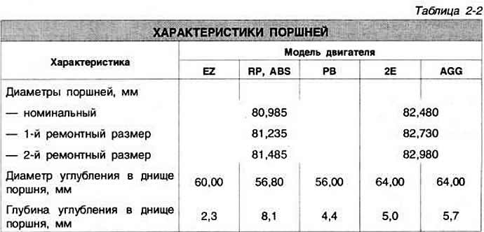
Remove the piston rings and clean the pistons from carbon deposits. Determine the degree of piston wear by measuring the diameter 10 mm from the edge of the piston skirt perpendicular to the axis of the piston pin (Fig. 2-9). The piston must be replaced if its diameter differs by more than 0.04 mm from the permissible values (Table 2-2).
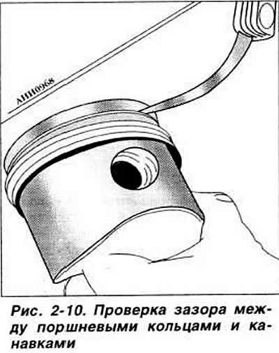
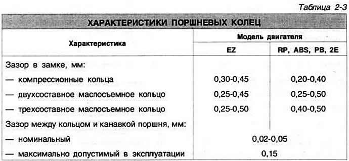
Replace piston rings or pistons if the clearances between the piston ends and grooves (Fig. 2-10) exceed the permissible values (Table 2-3).
Visitor comments