
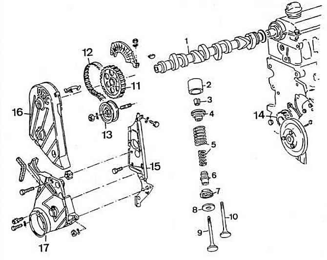
Figure 2-11. Timing mechanism details:
1 - camshaft;
2 - hydraulic pusher;
3 - cracker;
4 — the top basic plate of springs;
5 - valve springs;
6 - oil cap;
7 - lower support plate of springs;
8 - washer;
9 - exhaust valve;
10 - inlet valve;
11 - a gear pulley of a camshaft;
12 — a gear belt of a drive of a camshaft;
13 — a tension roller of a toothed belt;
14 - toothed pulley of the crankshaft;
15 — a back protective cover of a gear belt;
16 — the top protective cover of a gear belt;
17 - lower protective cover of the toothed belt.
An intermediate shaft with a toothed pulley is installed in the cylinder block. The shaft drives the oil pump and the ignition distributor, and on vehicles with an engine model «EZ» and fuel pump. The drive of the intermediate shaft is carried out by a toothed belt of the camshaft drive.
With the correct installation of the gas distribution mechanism, the label «FROM» on the flywheel corresponding to the TDC of the first cylinder. must be aligned with the mark in the hatch of the clutch housing. The mark on the camshaft sprocket must be located on the left side at the level of the plane of the cylinder head gasket. The mark on the intermediate shaft pulley must be aligned with the TDC mark of the 1st cylinder on the crankshaft pulley.
Visitor comments