



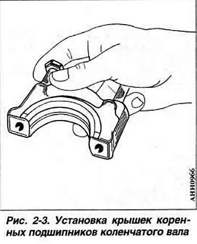
Install a clean cylinder block on the stand. Wipe the bed under the liners in the block and in the main bearing caps with a napkin. Install the liners in the cylinder block sockets, having previously wiped them and lubricated them with engine oil. The liners of the 1st, 2nd and 5th main bearings do not have lubrication grooves. The liners of the 3rd bearing supplied as spare parts have flanges. On the thrust half rings from axial displacement of the crankshaft on the cylinder block side, there is a protrusion directed toward the liners. Wipe the main and connecting rod journals of the crankshaft with a napkin, lubricate them with engine oil and install the shaft in the cylinder block. Install the main bearing caps in accordance with the marks applied to their outer surfaces (Fig. 2-3), tighten and tighten the cap mounting bolts to a torque of 6.5 kgf·m. Turn the crankshaft. Make sure it rotates freely with little force.
Check the axial free play of the crankshaft as specified in subsection "Crankshaft and flywheel". Install three piston rings into the corresponding grooves in the pistons, arranging their locks every 120°. Orient the lock of the upper compression ring in the plane of the crankshaft axis. On the lower compression and oil scraper rings there is a mark "Top" or "Oben" ("Top"), which should be facing upward when installing the ring in the groove.
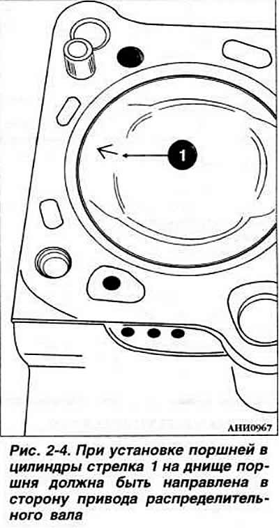
Match the pin to the connecting rod. The clearance in the "piston pin - connecting rod upper head bushing" joint is 0.017-0.021 mm. The maximum allowable clearance in operation is 0.03-0.07 mm. Before pressing in the pin, heat the piston in a water bath to 80°C. Install the unit on a press and, using a mandrel, press the piston pin into the piston and the upper head of the connecting rod. Install the retaining rings in the grooves of the piston bosses. Install the pistons, orienting the arrow stamped on the piston bottom, toward the camshaft drive side (Fig. 2-4).
Lubricate the pistons and piston rings with engine oil, compress the piston rings in the grooves with the appropriate mounting sleeve and insert the pistons with the connecting rods into the cylinders taking into account the instructions in Fig. 2-5. Install the liners in the connecting rods and connecting rod caps in accordance with the marks made during disassembly, if worn liners are used. Lubricate the upper thrust half rings with engine oil and insert them into the middle main bearing seat with the antifriction layer towards the crankshaft cheeks. Lubricate and install the lower thrust half rings together with the middle main bearing cap. Install the connecting rods and caps on the crankshaft journals, while the ridges on the caps and the locking projections on the liners should be directed towards the intermediate shaft. Screw on the connecting rod bolt nuts, then tighten them to a torque of 3.0 kgf·m and turn them further 180°.

Install the rear oil seal holder with a new cardboard gasket. Press the oil seal into the holder using mandrel 2003/1. Install the flywheel, ensuring that the surface under the clutch driven disk protrudes relative to the cylinder block within 30.50-32.10 mm. Tighten the mounting bolts to a torque of 10 kgf·m.
On cars manufactured since the 1991 model year, the flywheel mounting bolts must be replaced each time the flywheel is removed. The threaded portion of the bolts is coated with locking glue and tightened in two steps:
- 1st technique: torque 6 kgf·m;
- 2nd step: turn 90° further.
On cars manufactured since the 1991 model year, the crankshaft toothed pulley mounting bolt must be replaced with a 12-sided head bolt if the latter is removed. In this case, a washer is not placed under the bolt. Before installing the pulley, lubricate the threaded part and the flange of the bolt head with engine oil. Tighten the bolt in two stages:
- 1st reception: 9 kgf·m;
- 2nd step: turn 90° further.
If necessary, install a spacer washer between the flywheel and the crankshaft flange. Install a lock washer on the flywheel with the beveled edge facing the flywheel. Pre-apply special glue to the mounting bolts. Install the front crankshaft oil seal holder with a new cardboard gasket. Press the new oil seal into the holder using mandrel 3083. Insert the intermediate shaft into the cylinder block. Install the holder with the pressed-in oil seal and sealing gasket on the intermediate shaft. Install the oil pump, having first checked its technical condition. Install the oil sump with a new gasket. Install the cylinder head. Install the camshaft drive belt. Install the water pump.
Visitor comments