



On vehicles with a fuel injection system, disconnect the air supply hose from the throttle body or central injection unit. Remove the air filter. Disconnect the electrical wires from the carburetor and disconnect the carburetor plug connectors. Disconnect the electrical wiring from the fuel injection system units and sensors. Disconnect the throttle cable and vacuum hoses from the carburetor and remove the carburetor. Remove the intake manifold. Unscrew the flange of the muffler inlet pipe from the exhaust manifold. Remove the exhaust manifold. Disconnect the high-tension wire bundle and unscrew the spark plugs. Disconnect the cooling system hoses going to the radiator and heater from the cylinder head. Remove the cylinder head cover. Unscrew the cylinder head mounting bolts. Remove the cylinder head. Clean the removed parts and determine their condition by visual inspection. Use special detergents when cleaning the mating surfaces of the cylinder head. It is prohibited to use objects that can leave scratches or abrasive materials for these purposes.
Replace the sealing gaskets each time the cylinder head is removed.
When installing the cylinder head, install a new cylinder head gasket with the "Oben" mark ("Top") toward the plane of the head. Insert bolts 8 and 10 (Fig. 2-21) into the cylinder head holes or install centering pins into the holes for these bolts in the cylinder block. Then install the cylinder head. Install new washers and cylinder head mounting bolts.
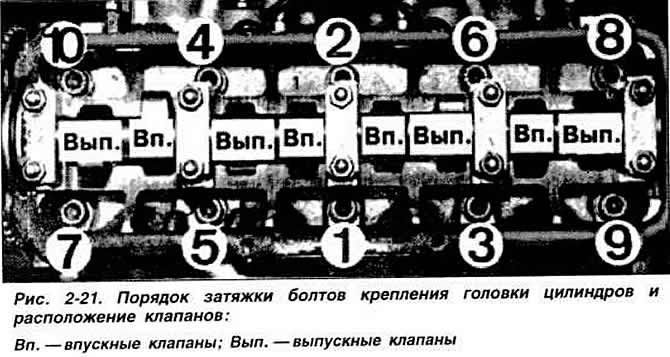
Gradually tighten the cylinder head mounting bolts, observing the specified order (Fig. 2-21) and tightening torques. Tighten the cylinder head mounting bolts very carefully. Before tightening, check the accuracy of the torque wrench. Tighten the bolts on a cold engine in three stages:
- 1st technique: torque 4 kgf·m;
- 2nd technique: torque 6 kgf·m;
- 3rd step - tighten 180° with a rigid wrench without stopping. Tightening in two steps of 90° is allowed.
Warning: Additional tightening of cylinder head bolts on a warm engine, as part of maintenance or after repairs on gasoline engines is not permitted.
Install the camshaft drive belt as shown below. Install the timing belt guards. Install the alternator and coolant pump drive belt, tensioner bar and adjust the belt tension.
Install the exhaust manifold and the flange of the muffler inlet pipe. Install the intake manifold and carburetor. Connect the cooling and heating hoses to the cylinder head. Install the cylinder head cover. Connect the vacuum hoses to the carburetor, connect the plug connectors, electrical wires and carburetor control cables. Connect the electrical connectors and pipes to the fuel injection system. Install the air filter, spark plugs and high-voltage wires. Fill the engine cooling system with coolant. Connect the wire to the negative terminal of the battery. Start the engine, listen to its operation and, if necessary, adjust the ignition timing and engine idle speed.
Disassembly, assembly, technical condition check and repair of the cylinder head
Remove the cylinder head as described above and install it on a stand. When disassembling the cylinder head, mark the parts to be removed so that they can be put back in their original places when reassembling. Remove the spark plugs.
Remove bearing caps No.5, 1 and 3 of the camshaft, then alternately crosswise unscrew the nuts of the studs securing bearing caps No.2 and 4.
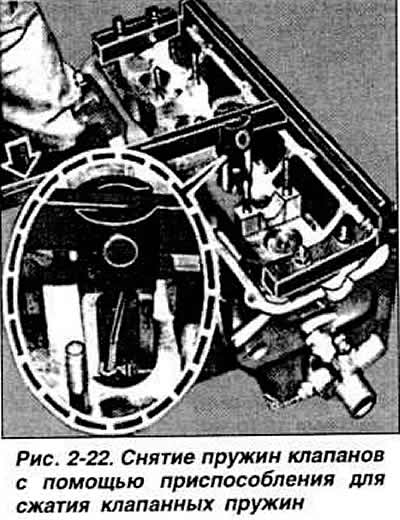
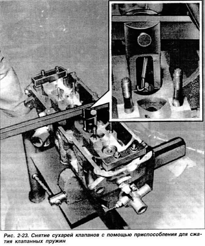
Remove the camshaft from the cylinder head supports and remove the valve tappets. Install a valve spring compressor or a special VW 541 device for removing and installing valve crackers on the cylinder head and use pliers with pointed ends to release the valves from the crackers, having first pressed the lever of the special device (fig. 2-22 and 2-23). Remove the valve springs with the retainers. Remove the valve stem oil caps and spring support washers using pliers. Remove the valves. Mark the position of the removed parts so that the parts that are not to be replaced are returned to their original position during assembly. Clean the parts. Check the degree of wear of the valve guide bushing seats and the clearance between the bushings and the valve stems. Insert a new valve into the guide bushing so that the end face of the valve stem is flush with the edge of the guide bushing, and determine the clearance between the end face of the stem and the edge of the guide bushing using the VW 387 device with an indicator. Replace the guide bushings if the indicator reading exceeds 1 mm for the intake valve bushings and 1.3 mm for the exhaust valve bushings. Check that the flatness of the mating surface of the cylinder head is not damaged. using a straightedge and feeler gauge sets. If necessary, grind the mating surface of the cylinder head within acceptable limits. Check the condition of the valves and valve springs.
Check the condition of the valve seats and grind them if necessary. Grinding is performed with a special tool and within the permissible limits.
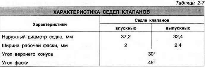
In case of grinding of valve seats, to ensure normal operation of hydraulic valve tappets, it is necessary to maintain a minimum distance "a" (fig. 2-24 and 2-25) between the end of the valve stem and the upper plane of the cylinder head, which for intake valves should be equal to 33.80 mm. for exhaust valves - 34.10 mm.

Fig. 2-24. Dimensions for grinding valve seats:
Vp — - intake valve seat;
Ext. - exhaust valve seat;
P - cylinder head plane;
a — outer diameter of the working chamfer of the exhaust valve seat;
b — distance from the end face of the working chamfer of the intake valve seat to the plane of the cylinder head;
c — width of the working chamfer of the exhaust valve seat;
d — outer diameter of the working chamfer of the inlet valve seat;
e — distance from the end of the working chamfer of the intake valve to the plane of the cylinder head;
f — width of the working chamfer of the inlet valve seat.
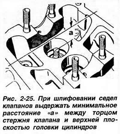
The shrinkage of the working chamfer of the valve seat must not exceed a value equal to the difference between the value "a" before grinding the valve seat and the minimum value "a" after grinding.
If necessary, grind the working chamfers of the inlet valves. The working chamfers of the outlet valves are not subject to grinding; grinding of the outlet valves is allowed; in other cases, they are subject to replacement.
Before assembly, thoroughly clean the cylinder head, as well as after grinding the valve seats and lapping the valves. Check the degree of wear of the camshaft, the maximum radial runout of the middle journal of the shaft and its axial movement, which must be within acceptable limits.
Insert the valves into the guide bushings, after lubricating the valve stems with engine oil.
The technical condition of the hydraulic tappets is checked while the engine is running, since their design is non-disassemblable and cannot be repaired. To check, start the engine and leave it running until the first activation of the electric fan of the cooling system.
Maintain the engine crankshaft speed at 2500 rpm for 2 minutes.
If you hear noise in the valve mechanism, determine the faulty tappet as follows:
- remove the cylinder head cover;
- turn the engine crankshaft clockwise by the pulley mounting bolt so that the camshaft cam heads corresponding to the valves of the cylinder being checked are facing the hydraulic tappet;
- press the plunger with a wooden or plastic wedge and measure the free travel of the plunger, which should be no more than 0.10 mm before the valve opens. If it is more, the plunger must be replaced.
Warning: After installing a new tappet, pre-filled with oil and bled, the engine may not be started earlier than 30 minutes later to prevent the valves from hitting the pistons.
When assembling the cylinder head, install the valve spring support washers in place and insert the valves into the guide bushings. Using mandrel 10 204, press new oil deflector caps onto the valve guide bushings, having first put the protective caps on the valve stems. Install the valve spring support washers in place. Install the springs and spring plates. Install the crackers using a valve spring compressor. Insert the valve tappets into the head holes, having first lubricated them with engine oil to facilitate installation. Pay special attention to the fact that the tappets are returned to their previous position. Lubricate the bearing journals and cams of the camshaft with engine oil and place it in the cylinder head supports so that the cams of the first cylinder are directed upwards. Install bearing caps No.2 and 4 alternately crosswise, screw the nuts onto the mounting studs, but do not tighten the nuts completely. Install bearing caps No.5, 1 and 3 and pre-tighten the fastening nuts, taking into account the offset position of the caps of these bearings relative to the axis. Install the bearing caps finally in the seats, lightly hitting the front flange of the camshaft with a mallet. Finally tighten the fastening nuts of the bearing caps to the required torque, starting with the nuts of bearing cap No.5.
Press in a new camshaft oil seal using tool 10 203. Install the camshaft toothed pulley and tighten its mounting bolt to the required torque. Screw in the spark plugs
To remove the camshaft drive belt, disconnect the wires from the battery terminals. Loosen the alternator mounting bolts and remove the drive belt. Remove the crankshaft pulley. Remove the toothed belt protective covers. Disconnect the high-voltage wire bundle. Unscrew the spark plugs from the cylinder head sockets. Turn the crankshaft to the TDC position of the compression stroke of piston No.1, aligning the mark on the flywheel with the installation protrusion on the clutch housing and placing the mark on the camshaft pulley at the level of the cylinder head gasket. Loosen the tension roller axle mounting nut. Remove the camshaft drive toothed belt.
Note: Do not turn the camshaft when any of the pistons is at TDC.
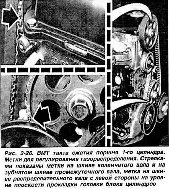
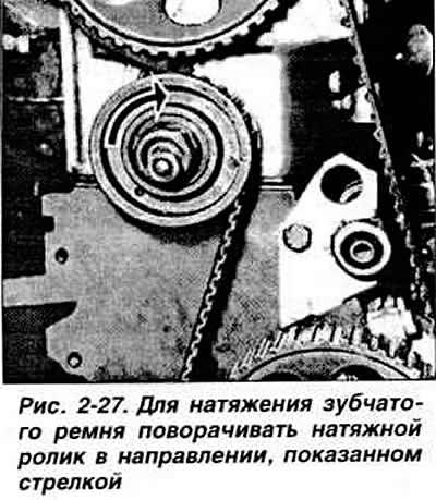
When installing, turn the camshaft to the TDC position of the compression stroke of piston No.1 cylinder, placing the mark on the camshaft pulley at the level of the cylinder head gasket (Fig. 2-26). Install the intermediate shaft toothed pulley in the correct position, aligning the mark on it with the TDC mark of piston No.1 cylinder on the temporarily installed crankshaft pulley. Install the crankshaft to the position corresponding to the TDC of the compression stroke of piston No.1 cylinder according to the marks on the flywheel and on the clutch housing. Put the toothed belt of the camshaft drive on the pulleys. Adjust the belt tension by turning the tension roller on the axle in the direction opposite to the direction of rotation of the toothed belt (Fig. 2-27).
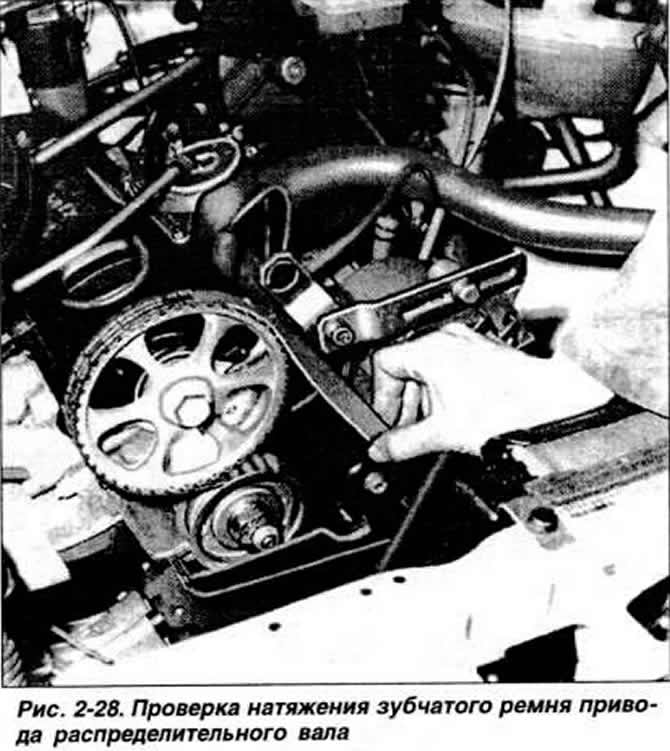
Turn the crankshaft two revolutions and check the correct adjustment of the toothed belt tension (Fig. 2-28). Remove the crankshaft pulley and install the toothed belt protective covers. Install the crankshaft pulley. Put on the generator drive belt and adjust its tension. Tighten the generator mounting bolts. Screw in the spark plugs and connect the high-voltage wires. Check and, if necessary, adjust the ignition timing. Connect the battery.
Visitor comments