
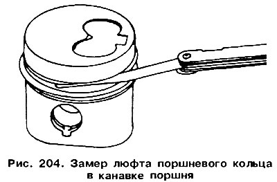
Measure a backlash between piston rings and regiments of grooves under rings in the way shown on fig. 204. If this measurement, measured with a dipstick, exceeds 0.20 for a compression ring or 0.15 mm for an oil scraper ring, this indicates wear of the ring or piston. Nominal clearance values are given in Table. 1. Then insert the piston rings one by one into the cylinders from the side of the cylinder block. In a turbocharged engine, the oil injectors must be unscrewed beforehand. With the piston upside down, push each ring down, approximately 20, while the rings will be perpendicular to the axis of the cylinder. Insert a feeler gauge into the locks of the rings to determine the gap in the lock (see fig. 74). For compression rings, the gap should be 0.30-0.50 mm, and for oil scraper rings - 0.25-0.40 mm. The maximum allowable gap in the lock for all types of rings is 1.0 mm.
If the gap is very small (this happens on new rings, which also need to be checked), then you can increase it by sawing the ends (see fig. 75). If the gap in the lock exceeds 1 mm, the rings should be replaced. Check the degree of wear of the piston pin and the bushing of the connecting rod head. A connecting rod that does not meet the requirements must be replaced with the rest of the connecting rods, even if they are in good condition. The connecting rod cap bolts and nuts should always be replaced. It is recommended to check the connecting rods for bending. Method for measuring backlash in connecting rod bearings described here.
Visitor comments