
Valve springs and valve guides
The valve springs must not be cracked and must be sufficiently resilient. To fully inspect the valve springs, a special spring test tool should be used. If not, then install the springs in a row on a smooth surface so that the closed knurling is at the bottom. Place a steel angle next to the spring and measure the gap between the top of the spring and the angle. The gap should not be more than 2.0 mm. Otherwise, the spring is skewed.
Valve guides
Check the valve guide in the following order:
- clean the valve guide bushing from soot by dragging a rag soaked in gasoline through the bushing back and forth;
- thoroughly clean the valve stem, and in order insert the valves into the guide bushings;
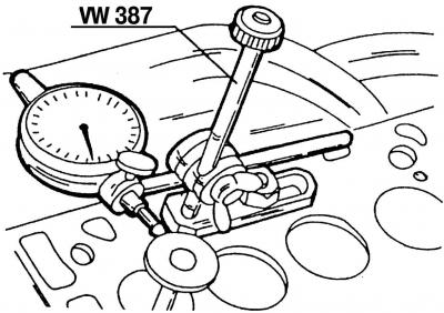
Pic. 113. Checking the runout of the valve stem inside the guide sleeve using a measuring device VW387
- check the runout of the valve stem inside the guide sleeve using the VW387 gauge (pic. 113) in the following way:
- install the measuring device VW387 with the appropriate bracket on the upper part of the cylinder head;
- pull the valve out of the hole as much as possible so that the end of the valve stem is finally stopped by the guide sleeve;
- rock the valve disc at the top from side to side and check the meter reading. If the value obtained is greater than 1.0 mm on the intake valves or 1.3 mm on the exhaust valves, the valve guide must be replaced.
The general condition of the cylinder head should also be checked. Can be used after grinding the cylinder head. If it has small scratches between the valve seats or between the valve seat and the first thread of the spark plug hole, as long as the scratches are not wider than 0.5 mm, then the cylinder head can be reground and reused.
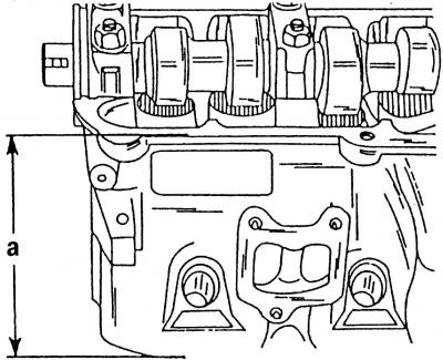
Pic. 114. Measuring the height of the cylinder head
After regrinding the cylinder head, the value of a (pic. 114) must be at least 132.60 mm. Measurements should be carried out either with a caliper or a measuring ruler, placing the cylinder head on a flat surface.
Press out the guide bushings from the cylinder head in the following order:
- inspect installed guide bushings. If the guide bushings have not yet been replaced, the valve guide bushings are not fastened and can be pressed out of the cylinder head on the camshaft side. If the guide bushings have already been replaced, the bushings will have a bond that can be seen from the camshaft side. In this case, the old guide sleeve must be pressed out from the side of the combustion chamber;
Pic. 115. Pressing out the valve guide. New bushings are pressed in from the same side
- the guide sleeve is pressed out of the cylinder head using a punch. To facilitate pressing out, the cylinder head can be heated. On the punch you need to screw the pin, which fits in size to the inside of the valve guide. Pressing out the original guide bushing, which has not yet been replaced, is shown in (pic. 115);
- When a valve guide is replaced, the valve itself also changes along with it. Then you need to grind the valve seats.
Press the guide bushings into the cylinder head in the following order:
- lubricate new guide bushings with engine oil before installation and press them from the side of the camshaft into the cold cylinder head so that the shoulder of the valve guide bush enters the cylinder head. The pressing pressure must not exceed 1 ton, otherwise the collar may be sheared off. The cylinder head must rest on a perfectly flat surface;
- after pressing, the valve guide must be machined with a special reamer 3120. If such a reamer is not available, then an adjustable reamer of 8.0 mm can be used, which must be regularly lubricated with a so-called cutting oil in order to avoid small notches in the hole after it - traces «crushing».
Note. If the guide bushing has been replaced, the valve seat should be lapped so that it is concentrically aligned with the new guide bushing.
Valve seats
Check the valve seats in the following order:
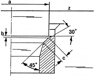
Pic. 116. Valve seats: a - valve seat diameter (see adjustment and control table); b - the maximum allowable amount of processing; c - valve seat width: for the intake valve - 2.0 mm, for the exhaust valve - 2.4 mm; z - lower edge of the cylinder head; 30°- upper correction angle; 45°- valve seat bevel angle
- Check all valve seats for wear and scratches. On the working chamfers of saddles (valve contact area) there should be no pitting, corrosion or damage. Minor damage can be repaired by grinding the seats with a 45°cutter. At the same time, remove as little metal as possible. You can grind both manually and with a grinder. If the seats are badly worn, they should be remilled. The shape of the chamfers of the valve seats is shown in (pic. 116); The angle values are suitable for exhaust and intake valves. The value of the diameter a of the valve seat should be taken from the tables of adjustments and control. This is especially important for intake valves, as they are not the same for some engines;
- To determine the size of the valve seat finish, take the following measurements:
- insert the valve into its guide sleeve and press the seat (flat head) valve;
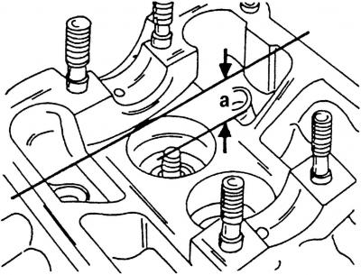
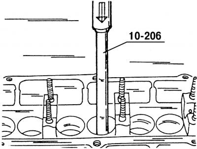
Pic. 117. Depth measurement during additional processing of valve seats. Dimension a is measured between the arrows
- measure interval a (pic. 117) between the top of the valve stem and the top edge of the cylinder head. To do this, place a measuring ruler on the plane of the cylinder head;
- Calculate the maximum and minimum allowable value of the measured value after milling a. On the intake valves, it should be 33.8 mm, on the exhaust - 34.1 mm;
- if the minimum distance is subtracted from the measured value, then the permissible value b will be obtained (pic. 116). This is necessary so as not to bore the valve seats in the cylinder head too much. Milling of valve seats is carried out if new guide bushings have been installed. For this you need:
- lightly machine the top edge of the valve seat with a 45°cutter and then a 30°cutter to reduce the width of the valve seat to 2.0 mm for inlet and 2.4 mm for exhaust valves. Processing should be stopped as soon as the dimensions of the valve seat have reached the specified values. The exhaust valve seats have diameter limiters. When processing, be careful not to damage these stops;
- in order not to bore the valve seats in the cylinder head too much, be sure to calculate the value b;
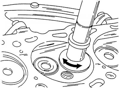
Pic. 118. Rubbing the valve with a suction cup. The suction cup should be rotated back and forth in the direction indicated by the arrows
- grind machined valve seats. To do this, apply a small amount of lapping paste to the valve seat and install the valve in the appropriate seat. Attach a suction cup to the valve and rotate the valve with it back and forth in the direction shown by the arrows (pic. 118). In order to grind the valve seat well, you need to periodically remove the suction cup, turn the valves a quarter of a turn, and then continue grinding;
- after lapping, carefully clean all parts from dirt and lapping paste;
- check the valve seat in place of the valve head and o-ring. A continuous, frosted ring should be visible on both parts;
- draw a few lines with a pencil on the ring on the valve head. Dashes should be drawn around the ring at intervals of approximately 1 mm. After that, carefully insert the valve into the guide sleeve, lower it onto the seat and turn it around 90°, applying a slight force to the valve;
- remove the valve and check if the pencil lines from the O-ring have disappeared;
- if the valve seat width matches the specified dimensions, then the cylinder head can be installed. Otherwise, the valve seats must be reworked or, at the very least, a new cylinder head must be installed.
Valves
All that is written about the valves of the VR6 engine (see point 2.3.3), is also true for the 2.0 liter engine. The dimensions of the valves are indicated in the table of adjustments and control.
Cylinder head
Wash the cylinder head thoroughly and clean the oil passages. Remove carbon deposits from the combustion chambers and from the surface of the exhaust channels with a wire brush. Thoroughly clean the contact surfaces of the cylinder head and cylinder block. Inspect the cylinder head. The bearings under the camshaft journals and in the holes for the valve lifters must not be scratched or damaged. Cracks in any places of the cylinder head are not allowed.
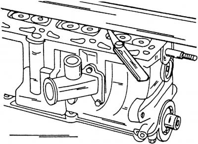
Pic. 119. Checking the cylinder head for deformation using a measuring ruler and a feeler gauge
Check the surface of the cylinder head for deformation (pic. 119).
To do this, place a measuring ruler on the cylinder head and use a feeler gauge to check the clearance along, across and diagonally. If it does not exceed 0.10 mm, then the cylinder head can be ground. If the gap in any place is larger, then the cylinder head should be replaced, since removing a larger layer of metal can adversely affect engine compression.
The cylinder head can be ground as long as its minimum height is a (pic. 114) not less than 132.60 mm.
Camshaft
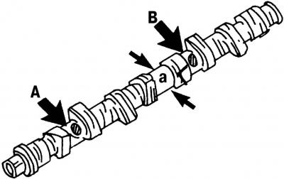
Pic. 120. Places for marking on the camshaft. Letters and numbers are embossed on the places shown by arrows
The camshaft of the ADY engine is marked in a certain way. At the location indicated by arrow A (pic. 120) embossed letter (B), in place B is the number (037). Since camshafts for other types of engines have different markings, it is recommended that you take the old one with you when buying a new camshaft.
Cam diameter a (pic. 120) on engines of this design range, reduced to 34.0 mm.
When inspecting camshafts, pay attention to the surfaces of the bearing journals (bearing locations), cams, which must be well polished and not damaged. If signs of seizing or deep marks are found, the camshaft must be replaced. Before installing the camshafts, carry out the following operations:
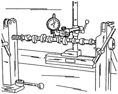
Pic. 47. Measuring the radial runout of the camshaft
- install the camshaft with the outer journals on two prisms, or clamp between the clamps of the lathe and install the measuring device (pic. 47) in place of the middle bearing (necks) camshaft;
- slowly rotate the camshaft and follow the readings of the measuring device. If, according to the readings of the device, the radial runout exceeds 0.01 mm, then the camshaft must be replaced, since it is deformed;
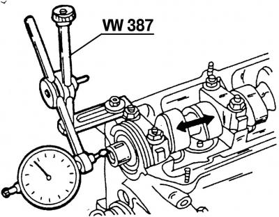
Pic. 121. Measuring the axial clearance of the camshaft
- to measure the camshaft end play, insert it into the cylinder head (without pushers), secure with the outer bearings and place the cylinder head on a flat surface. Install gauge VW387 (pic. 121) from the end of the cylinder head and rock the shaft back and forth in the longitudinal direction (in fig. 121 shown by arrows).
The axial clearance must not exceed 0.15 mm. Otherwise, the working surface of the bearing cover is worn out.
Visitor comments