



- unscrew all parts located on the cylinder head;
- clamp the cylinder head together with the clamp screwed to the exhaust manifold set screw in a vice;
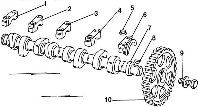
Fig. 108. Camshaft parts: 1 - bearing cover No.5; 2 - bearing cover No.4; 3 - bearing cover No.3; 4 - bearing cover No.2; 5 - nut, 20 Nm; 6 - bearing cover No.1; 7 - camshaft; 8 - segment key; 9 - bolt with washer, 80 Nm; 10 - camshaft gear wheel
- loosen the nuts of bearing caps No.5, 1 and 3 (Fig. 108) each by two turns evenly and crosswise until both caps are unscrewed, remove the caps;
Note: Cover #1 may contain an O-ring for the cylinder head cover.
- remove bearing caps No.2 and 4 in a similar manner;
- remove the camshaft from the cylinder head supports;
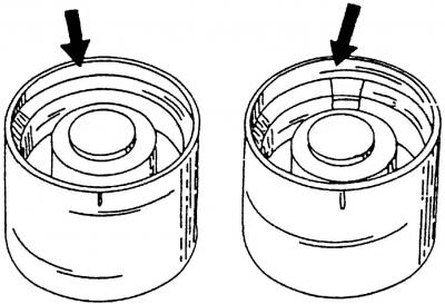
Fig. 109. Marking of hydraulic tappets
- apply scratch marks on the inner side of the pushers, i.e. the first pusher - one mark, the second pusher - two, etc. (Fig. 109), since they cannot be confused (the countdown is carried out from the side of the valve timing mechanism drive) and remove the pushers. Do not fold the pushers, but place them with the contact surface facing down;
Note: The tappets contain hydraulic valve clearance adjusting elements and must therefore be handled with care.
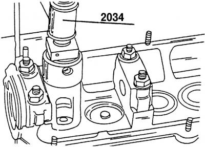
Fig. 110. Removing valves using puller 2034
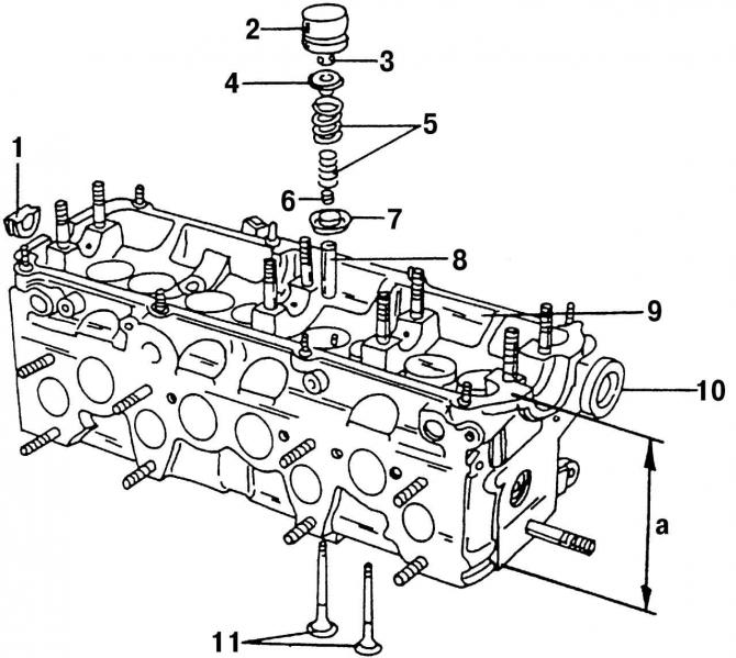
Fig. 111. Valve drive mechanism parts: 1 - semicircular sealing ring; 2 - hydraulic pusher; 3 - valve stem halves (crackers); 4 - upper valve spring plate; 5 - outer and inner valve springs; 6 - oil deflector cap; 7 - lower valve spring plate; 8 - valve guide bushing; 9 - cylinder head; 10 - camshaft oil seal; 11 - valves; a - cylinder head height
- the standard tool for removing and installing valves is tool number 2034 (Fig. 110). It is attached to the cylinder head. Release valve 11 (Fig. 111) from valve stem halves (crackers) 3, compressing springs 5 with tool 2034;
- to remove the valves, you can also use a piece of pipe that fits over the upper spring plate. You need to put something under the valve plate on the other side to secure it. Hit the pipe briefly with a hammer so that the halves of the valve stem come out. They will remain inside the pipe. But do not tear the pipe away from the spring plate, so as not to lose the halves of the valve stem;
- remove the upper plate 4 (Fig. 111) with springs 5, turn the cylinder head 9 and remove valve 11 from the bottom;
- remove the oil deflector cap 6 from the guide sleeve 8;
The original article is posted on the website (www.VWmanual.ru)
Note: Always replace the valve stem seals with new ones.
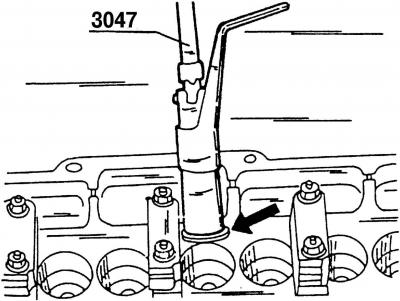
Fig. 112. Removing the lower valve spring plate using special pliers 3047
- using special tool 3047 (Fig. 112) or round-nose pliers, remove the lower plate 7 of the spring from the hole.
Visitor comments