
Before carrying out these works, the following recommendations should be observed:
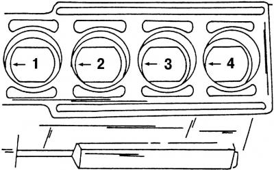
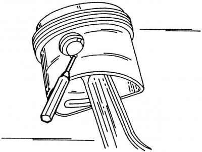
Pic. 130. Marking the bottom of the pistons before removing them
- mark (preferably colored) for each piston and its associated connecting rod. It is necessary to indicate the number of the cylinder from which the piston and connecting rod were removed. It is best to mark the piston with the cylinder number and an arrow pointing towards the front of the engine on the bottom of the piston (pic. 130);
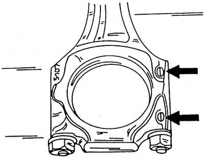
Pic. 55. Marking of the connecting rod and connecting rod bearing cap
Pic. 56. Assembling the connecting rod and connecting rod bearing cap. The arrows show the protrusions
- immediately after removal, mark the connecting rod and the connecting rod bearing cap on the side with the cylinder number (pic. 55). It is best to do this with a punch (for example, for cylinder No. 1 - one blow with a center punch, etc.). The connecting rod and connecting rod cap must be assembled so that both cast lugs are opposite each other (pic. 56);
Attention! Both cast projections must always be located on the side of the crankshaft pulley after installing the connecting rod.
- mark the bearing shells to match the connecting rod and connecting rod cap. Also color-code the top and bottom bearing shells on their rear side;
- if the pistons need to be replaced, measure the length of the piston pin immediately after disassembly. As experience shows, this size may be different on new pistons, so it is imperative to select pistons with pins of exactly the same length as the old piston pins had;
- when ordering new pistons, indicate the model of the car and its year of manufacture;
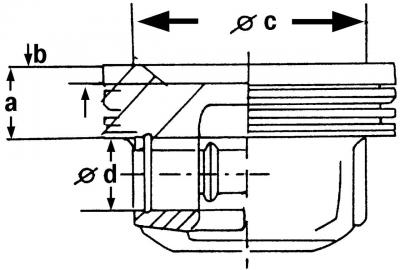
Pic. 131. Piston sectional view: a = 21.3 mm; b = 5.0 mm; c = 62.9 mm; d = 21.0 mm
- the geometric dimensions of the pistons differ from each other, so if you install a piston, for example, from an old engine, then you should measure the value b (pic. 131), which differs depending on the engine. The pistons to be installed must have the same b value. Different pistons also have differences in the value of a;
- piston diameters are presented in the table of adjustments and control.
Remove the pistons in the following order:
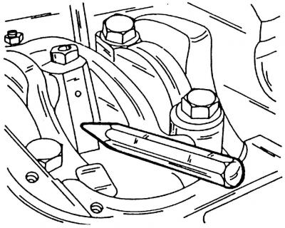
- remove the connecting rod caps and bearings and knock out the parts. If necessary, scrape off the oil deposits on the top of the cylinder with a scraper. To do this, turn the crankshaft slightly to lower the piston deeper into the cylinder bore. Be careful not to scratch the cylinder with the scraper;
Pic. 57. Removing the piston pin circlip
- using a sharp object or a small punch (pic. 57), remove the circlips located on each side of the piston pin. The notch in the piston pin hole makes it easier to use the punch;
- use a mandrel to knock out the piston pin. When hit, make sure that the mandrel does not pop out and hit the piston;
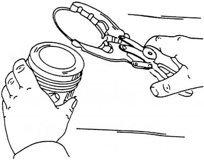
Pic. 58. Removing the piston ring with a puller
- mark piston rings (if they are installed again) and remove them through the piston crown with a puller (pic. 58). Remove the top piston ring first;
Attention! Never expand the piston rings too much.
Pic. 59. Removing the piston ring with metal strips
- if there is no piston ring remover, then metal strips can be inserted under the piston rings opposite each other (pic. 59). Place one of the metal strips under the piston ring lock to avoid scratches on the piston surface;
Note. Carefully pry the piston rings out of the piston grooves with a small screwdriver, as they break very easily.
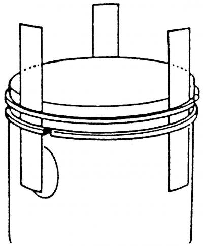
- remove the piston rings and tag them with the cylinder number. When inspecting the piston rings, make sure that one of the sides is marked «Oben» or «Top». When installing piston rings, this inscription must be visible from the side of the piston crown.
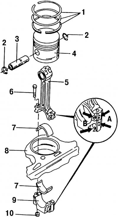
Pic. 132. Details of the connecting rod and piston group: 1 - piston rings; 2 - retaining ring; 3 - piston pin; 4 - piston; 5 - connecting rod; 6 - connecting rod mounting bolt; 7 - connecting rod bearing shell; 8 - cylinder block; 9 - connecting rod bearing cover; 10 - connecting rod nut; A - marks on the connecting rod and cover; B - the position of the cast protrusions
The details of the connecting rod and piston group of the engine are shown in fig. 132. Particular attention should be paid to the places with the letters A and B, which indicate important points on the location and orientation of the parts of the connecting rod and piston group.
Visitor comments