
- generously lubricate the valve stems with engine oil and insert them into the appropriate guide bushings;
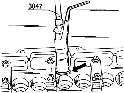
Pic. 112. Removing the lower plate of the valve springs using special pliers 3047
- using special forceps 3047 (pic. 112) install the lower valve plates;
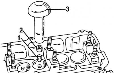
Pic. 122. Installing the oil seal: 1 - plastic sleeve; 2 - oil deflector cap; 3 - special tool 3129
- using special tool 3 (pic. 122), install oil seals 2, for which:
- fit the plastic sleeve 1 with special tool 3129 onto the protruding part of the valve guide;
- lubricate the oil deflector cap 2 well with engine oil and put it on the plastic sleeve;
- put special tool 3129 on the oil seal and carefully fit it into the guide sleeve;
Note. Installing the seals without the use of the special tool 3129 may damage them, resulting in increased oil consumption.
- after lapping the valves, each valve must be installed in the seat to which it was lapped;
- install in the holes of the cylinder head one inner and one outer spring for the corresponding valve (if old springs are installed);
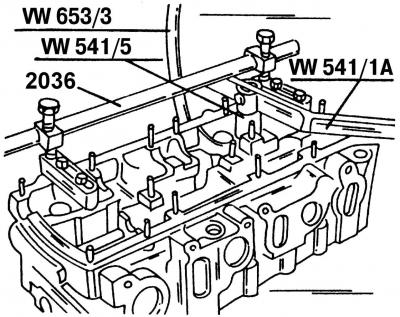
Pic. 36. Removing the valves using a special tool from the company «Volkswagen»
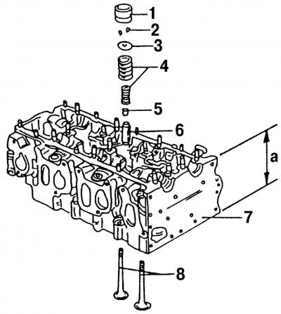
Pic. 37. Details of the valve drive mechanism: 1 - hydraulic pusher; 2 - valve stem halves (crackers); 3 - upper plate of the valve spring; 4 - valve springs; 5 - oil deflector cap; 6 - valve guide sleeve; 7 - cylinder head; 8 - valves; a - cylinder head height
- put on the top valve spring cap. Install the valve puller (pic. 36) to compress the springs. If the end of the valve stem protrudes from the upper valve spring seat, then both halves of the valve stem must be installed (crackers) 2 (pic. 37) into the cylindrical grooves of the rod and gently press the valve puller;
- Use a plastic mallet to hit the top of the valve stem. In this case, incorrectly installed crackers will fly out of the cylindrical groove;
Pic. 109. Marking of hydraulic pushers
- insert the hydraulic tappets according to the previously marked marks (pic. 109) in holes (pre-lubricated with engine oil);
Note. Before final installation of the tappets, read the instructions for the hydraulic tappets (see point 3.3.6), to avoid damage to the engine when it is first started after work has been carried out.
- generously lubricate the necks with engine oil (bearing locations) camshaft;
- Place the camshaft in the cylinder head bearings and rotate them several times. Install the camshaft so that both cams of the first cylinder on the shaft look up;
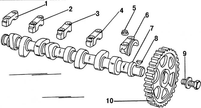
Pic. 108. Details of the camshaft: 1 - bearing cover No. 5; 2 - bearing cap No. 4; 3 - bearing cap No. 3; 4 - bearing cover No. 2; 5 - nut, 20 Nm; 6 - bearing cover No. 1; 7 - camshaft; 8 - segment key; 9 - bolt with washer, 80 Nm; 10 - camshaft gear
- put on bearing caps no. 2 and 4 (pic. 108) and hand tighten the nuts;
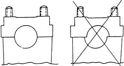
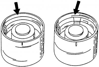
Pic. 123. Installing the camshaft bearing cap on the cylinder head
- check that the bearing caps are correctly installed as shown in fig. 123, and only then screw the fastening nuts alternately crosswise in several steps and tighten them to a torque of 20 Nm. Due to the uniform tightening of the valve springs, they will slowly compress, and thus it will be possible to avoid misalignment of the camshaft;
- install bearing caps no. 5, 1 and 3 in the same way;
- turn the camshaft several times to make sure that it is not pinched anywhere;
- when installing the oil seal, lubricate the sealing surface with engine oil (the rolling surface of the camshaft should also be lubricated) and make sure that the side of the stuffing box on which the spring is located is directed into the cylinder head. To install the stuffing box, you can use a pipe, which must fully match the size of the outer part of the stuffing box. Put the seal straight (without distortion) and press it in until its outer surface is completely inside. You can install the oil seal in the manner described in paragraph 3.6.4 for a new front crankshaft oil seal;
- install the intake and exhaust manifolds on the cylinder head (be sure to use new gaskets).
Visitor comments