



- generously lubricate the inner surfaces of the cylinders with engine oil;
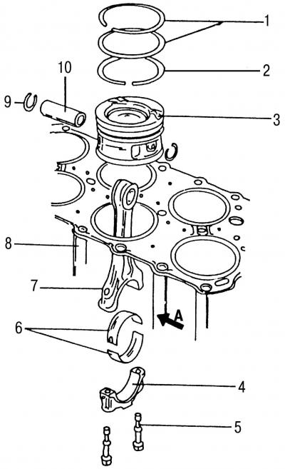
Fig. 63. Piston group parts: 1 - compression piston rings; 2 - oil scraper ring; 3 - piston; 4 - connecting rod cover; 5 - connecting rod mounting bolt; 6 - connecting rod bearings; 7 - connecting rod; 8 - cylinder block; 9 - retaining ring; 10 - piston pin; arrow A points towards the front of the engine
- lay out all the connecting rods according to the cylinder numbers. The cast projections on the connecting rod and connecting rod cap should be directed towards the crankshaft pulley (Fig. 63). After installing the connecting rods, the cast projections should be located on the other side of the arrow;
- the arrows on the bottom of the pistons should point towards the front of the engine;
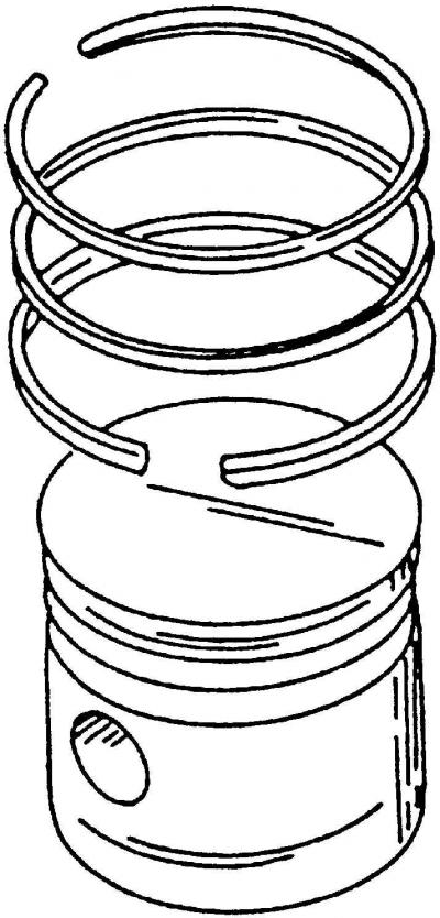
Fig. 134. Location of piston ring locks relative to each other
- position the piston ring locks relative to each other at an angle of 120° along the cylinder surface (Fig. 134);
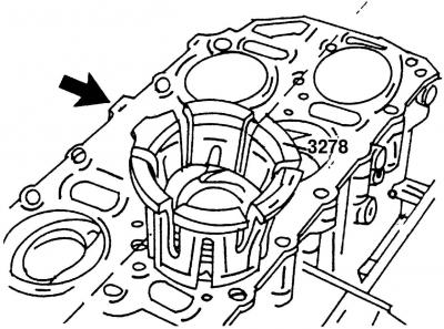
Fig. 66. Installing the piston using the special tool VW3278
- place the 3278 compression band clamp on the piston rings (Fig. 66) and press the piston rings into the piston grooves;
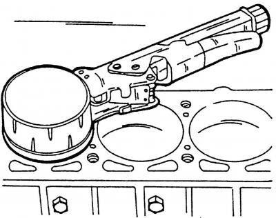
Fig. 67. Alternative tension band clamp for installing pistons
- for this purpose, you can use the one used by the company "Volkswagen" installation tool - tension band clamp (Fig. 67);
- check that the piston rings are fully seated in their grooves;
- turn the crankshaft so that the two crankpins of the crankshaft are at BDC;
- install the connecting rod bearing shell into the connecting rod;
- insert the connecting rod from above into the cylinder bore. To do this, lay the engine on its side so that the connecting rod can be directed towards the crank pin. Make sure that the cylinder bore and the connecting rod journal are not scratched;
- insert the pistons so that the piston rings enter the cylinder holes one by one and the connecting rod heel sits on the crankshaft journal;
- insert the second bearing shell into the bearing cap so that the bent tab of the shell fits into the groove of the bearing cap. Lubricate the surfaces of the shells with engine oil;
- press the connecting rod cap onto the connecting rod and tap it lightly. Lubricate the connecting rod mounting bolts with engine oil and screw them in;
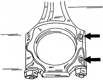
Fig. 56. Connecting rod and connecting rod bearing cap assembly. Arrows indicate protrusions
- be sure to double check that both castings are positioned together (Fig. 56). Both castings on the connecting rod and connecting rod cap should be positioned opposite each other and pointing towards the pulley;
- alternately tighten the connecting rod bearing mounting bolts to a torque of 30 Nm, then tighten them another 90° (a quarter turn);
- after installing the connecting rod, turn the crankshaft several times to make sure that it rotates easily and without sticking;
- double check all connecting rod markings to ensure piston arrows are pointing in the correct direction;
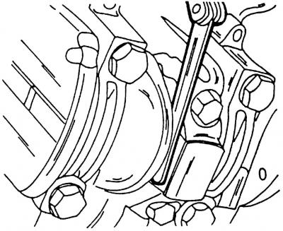
Fig. 68. Measuring the axial clearance between the side plane of the connecting rod bearing and the side surface of the crankshaft
- using a feeler gauge (Fig. 68), measure the axial clearance of the connecting rods installed on the crankshaft to assess the degree of wear of the parts. To do this, press the connecting rod to one side so that you can insert the feeler gauge. If you can insert a feeler gauge thicker than 0.37 mm, then most likely the connecting rods are worn out at the pressure points. In the worst case, the pressure points of the crankshaft are worn out;
- install the oil pan (see subsection 4.1);
- all further assembly work is carried out in the reverse order of disassembly.
Visitor comments