



- inspect the crankshaft. Cracks in any place of the crankshaft are not allowed. Scratches, nicks and marks are not allowed on the surfaces mating with the working edges of the seals;
- make precise measurements of the main and connecting rod bearing journals. During repairs, they can be reground up to three times with a reduction in diameter. After this, thicker repair liners are installed;
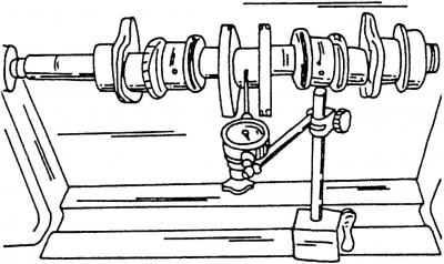
Fig. 138. Measuring the crankshaft runout in the area of the middle journal
- clamp the crankshaft between the holders of a lathe, or install the outer main journals on two prisms (Fig. 138) and check the runout on the main journal of the middle support with an indicator. The runout should not exceed 0.06 mm, otherwise the shaft should be replaced;
- measuring clearances in main and connecting rod bearings using a piece of plastic wire from the kit "Plastigage", is carried out in the same way as for the VR6 engine (see p. 2.6.2);
- if you do not have Plastigage plastic wire, the runout of the main and connecting rod bearings can be measured in the following way:
- install the bearing caps together with the inserted liners into the cylinder block and tighten the mounting bolts to a torque of 65 N·m. The liners must be installed in their original places;
- if the runout of connecting rod bearings is measured, insert the liners into the connecting rods and connecting rod caps, and tighten the caps with old nuts to a torque of 30 N·m;
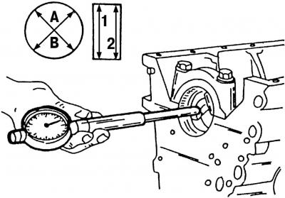
Fig. 139. Measuring the diameter of installed bearing shells. The measurement should be carried out in directions A and B, as well as in directions 1 and 2
- measure the diameter of the installed bearing shells using a measuring device (Fig. 139). Pay particular attention to the directions of measurement A and B, as well as the measurement locations 1 and 2. In this way, you can detect irregularities in roundness (A and B) as well as conicity (1 and 2). Record the measurement results for each individual bearing;
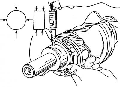
Fig. 140. Measuring the diameter of the main bearing journal. The diameter of the connecting rod journals can be measured in the same way
(The original can be viewed on the portal www.VWmanual.ru)
- measure the diameters of all bearing journals with a micrometer. Pay attention to the measurement locations (fig. 140, shown by arrows). Record the measurement results for each bearing journal;
- runout of main and connecting rod bearings and the difference between the measured internal diameters of the bearing bores and the bearing diameters.
Note: To check the connecting rod bearing runout, rotate the crankshaft and measure the next two connecting rod journals as described above.
Visitor comments