
- inspect the crankshaft. Cracks anywhere on the crankshaft are not allowed. On surfaces mating with the working edges of the seals, scratches, nicks and marks are not allowed;
- make accurate measurements of the journals of the main and connecting rod bearings. When repairing, they can be reground up to three times with a decrease in diameter. After that, repair liners of increased thickness are installed;
- clamp the crankshaft between the lathe holders (or install extreme main journals on two prisms) and check the runout on the main bearing journal with an indicator. The runout should not exceed 0.06 mm, otherwise the shaft should be replaced;
- measure the clearances in the main and connecting rod bearings, for which:
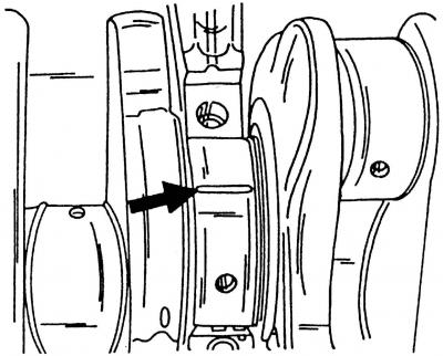
Pic. 83. The location of the plastic wire for measuring the clearance in the main or connecting rod bearings
- carefully clean the working surfaces of the inserts and the corresponding neck and place a piece of plastic wire on the surface of the neck (pic. 83);
- install a connecting rod with a cap or a main bearing cap on the neck, depending on the type of neck to be checked, and tighten the nuts or fastening bolts. Tighten the nuts of the connecting rod bolts to a torque of 30 Nm, and the bolts of the main bearing caps to a torque of 30 Nm;
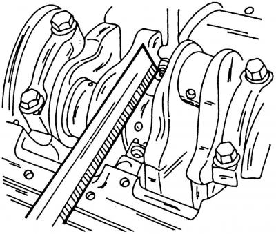
Pic. 84. Measuring the clearance in the main or connecting rod bearings
- remove the cover and on the scale of the measuring ruler included in the Plastigage flattening kit, at the widest point of the plastic wire (pic. 84), determine the size of the gap;
- if the gap is less than the limit, then these liners can be used again. If the gap is greater than 0.1 mm, replace the liners on these necks with new ones. If the crankshaft journals are worn out and are ground to a repair size, then replace the liners with repair ones (increased thickness).
Visitor comments