
- generously lubricate the valve stems with engine oil and insert them into the appropriate guide bushings;
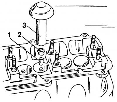
Pic. 49. Installing the oil seal: 1 - plastic sleeve; 2 - oil deflector cap; 3 - special tool 3129
- using special tool 3 (pic. 49), install oil seals 2, for which:
- push the plastic sleeve 1 of special tool 3129 onto the protruding part of the valve guide;
- lubricate the oil seal well with engine oil and put it on a plastic sleeve;
- put the special tool 3129 on the oil seal and carefully push the guide bush;
Note. If the valve stem seals are installed without the use of special tool 3129, they may be damaged, resulting in increased oil consumption.
- if the valves were lapped, then each valve must be installed in the seat to which it was lapped;
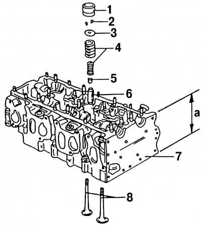
Pic. 37. Details of the valve drive mechanism: 1 - hydraulic pusher; 2 - valve stem halves (crackers); 3 - upper plate of the valve spring; 4 - valve springs; 5 - oil deflector cap; 6 - valve guide sleeve; 7 - cylinder head; 8 - valves; a - cylinder head height
- install in the holes of the cylinder head one inner and one outer spring 4 (pic. 37) for the corresponding valve (if old springs are installed);
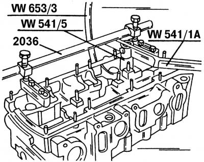
Pic. 36. Removing the valves using a special tool from the company «Volkswagen»
- put on the upper plate 3 of the valve spring. Install the valve puller (pic. 36), to compress the springs. If the end of the valve stem protrudes from the upper valve spring seat, both halves of the valve stem must be installed 2 (pic. 37) into the seat of the rod and gently press the valve remover;
- insert the hydraulic tappets in accordance with the previously marked risks into the holes, having previously lubricated them with engine oil;
- generously lubricate the necks with engine oil (bearing locations) camshafts;
- Place the camshafts in the cylinder head bearings and rotate them several times. Orient the camshafts so that both cams of the first cylinder on the two shafts look up;
- Mount both camshafts in the cylinder head as follows.
Mounting the camshaft of cylinder bank 1, 3 and 5
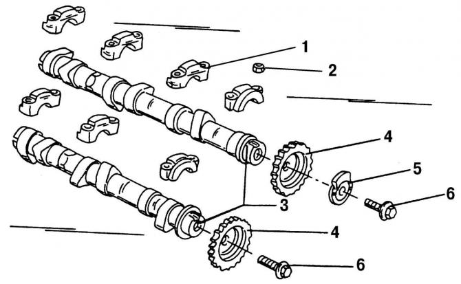
Pic. 31. Components of camshafts with bearing caps and sprockets: 1 - camshaft bearing cover; 2 - nut, 20 Nm; 3 - camshafts; 4 - camshaft sprockets; 5 - drive mechanism of the Hall sensor; 6 - bolts, 100 Nm
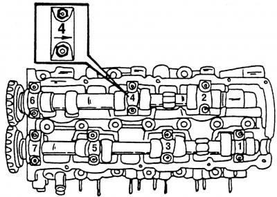
Pic. 34. Numbering of camshaft bearing caps. Each cover has an arrow showing the installation direction
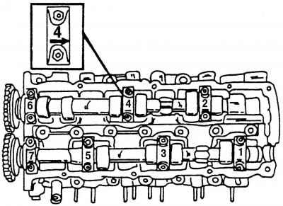
Pic. 50. Numbering of camshaft bearing caps
Liberally lubricate the inside of the bearing caps with engine oil and install bearing caps 3 and 5 on the cylinder head (pic. 34), and bearing caps 1 (pic. 31) camshaft in accordance with fig. 50:
Note. The numbers on the installed bearing caps should read from the exhaust side, and the arrows on the installed caps should point towards the crankshaft flywheel.
- tighten the four nuts alternately, crosswise in several stages and tighten them to a torque of 20 Nm. Due to the uniform tightening of the valve springs, they will slowly compress, and thus it will be possible to avoid misalignment of the camshaft;
- install bearing caps 1 and 7 in the same way;
- rotate the camshaft several times to make sure it is not pinched anywhere.
Mounting the camshaft of cylinder bank 2, 4 and 6
Liberally lubricate the inside of the bearing caps with engine oil and install bearing caps 2 and 6 on the cylinder head (pic. 34), and bearing caps 1 (pic. 31) camshaft, in accordance with fig. 50:
Note. The numbers on the installed bearing caps should read from the exhaust side, and the arrows on the installed caps should point towards the crankshaft flywheel.
- tighten the four nuts alternately, crosswise, in several stages and tighten them to a torque of 20 Nm. Due to the uniform tightening of the valve springs, they will slowly compress, and thus it will be possible to avoid misalignment of the camshaft;
- install the bearing cover 4 in the same way;
- rotate the second camshaft several times to make sure it is not pinched anywhere;
- put the sprockets on the camshafts. The sprockets must be installed on the shafts on which they stood before disassembly. Make sure that the sprockets are fixed with stoppers;
- on one of the camshafts, install the leash of the Hall sensor drive mechanism 5 (pic. 31);
- install sprockets 4 on the camshafts (pic. 31) drive. The mating surfaces of the driver and drive sprocket must be dry;
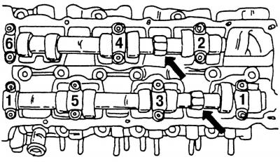
Pic. 32. Fixing camshafts. The arrows show the hexagons designed to fix the camshafts
- tighten bolts 6 (pic. 31) fastening sprockets, fix the camshafts in a fixed position using the hexagons (pic. 32) and tighten both sprocket bolts to 100 Nm. After that, unlock the camshafts;
- clean the surface of the camshaft cover and apply sealant AMV 188 002 02 to it;
- install the cover. First tighten the bolts in turn by hand, then tighten them in a circle with a tightening torque of 10 Nm. Check on the inside of the cover whether the O-ring is inserted, which should be in the cover;
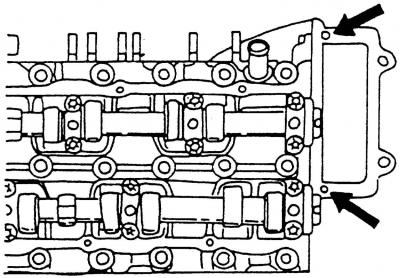
Pic. 51. Cleaning holes. The arrow shows the places for cleaning holes with a diameter of 3 mm
- if both camshafts (or only one camshaft) were removed with the engine installed, both 3 mm holes must be cleaned before installing the camshaft cover (pic. 51, shown by arrows) in the cylinder head cover and lubricate with sealant AMV 188 002 02;
- install the ignition coil;
- install on the cylinder head all previously removed parts, the number of which depends on the amount of repair work being carried out. Except for the parts that are installed when mounting the cylinder head in order not to do the same job twice.
Visitor comments