
English Русский
Български
Беларускі
Український
Српски
Hrvatski
Română
Polski
Slovenský
Magyar
  |  Articles  |  Sitemap  |  Contacts  |    |
Car maintenance Ford Car maintenance Hyundai Car maintenance Chevrolet Car maintenance BMW Car maintenance Audi Car maintenance Opel Car maintenance AvtoVAZ
VWmanual.ru


Main   Passat   Golf   Polo   Touareg   Tiguan   Sharan   Transporter   Others  
Sharan 1 (1995-2000)

Additional air supply system (VW Sharan 1)

  • Main
  • Sharan
  • Sharan 1
  • Petrol engines
  • Engine repair 2.8 l (AAA)
  • Additional air supply system
            0


This system forces air behind the exhaust valves for 65 seconds at an engine coolant temperature between 15° and 35°C. As a result, oxygen-rich exhaust gases leave the engine, which promote afterburning and allow the catalytic converter to warm up faster. The operation of the additional air supply system is controlled by the Motronic ECU via the secondary pump relay to the secondary air inlet valve and the combination valve.

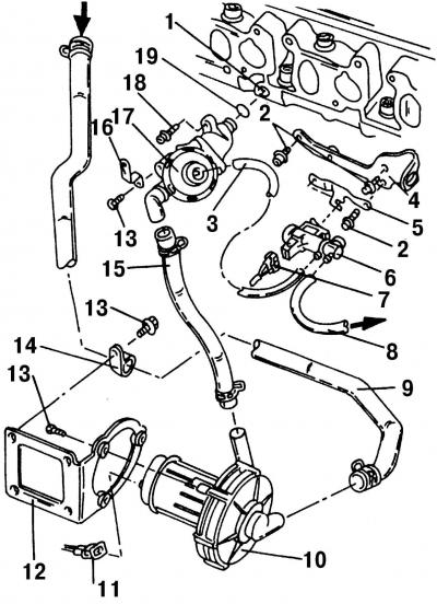
Fig. 99. Elements of the additional air supply system: 1 - air channel in the cylinder head; 2 -…

Fig. 99. Elements of the additional air supply system: 1 - air channel in the cylinder head; 2 - bolt, 25 Nm; 3 - vacuum hose; 4 - lifting eye; 5 - holder; 6 - additional inlet valve */**; 7 - plug-in block; 8 - vacuum hose; 9 - inlet hose; 10 - Air pump motor*; 11 - plug-in block; 12 - holder; 13 - bolt, 10 Nm; 14 - Hose clamp; 15 - pressure hose; 16 - holder; 17 - combination valve; 18 - bolt, 15 Nm; 19 - O-ring ___________ * The condition of this part is monitored by the self-diagnosis device. ** The condition of the part is monitored in the "final conclusion on malfunctions"


After each subsequent engine start and until the engine temperature reaches 85°C, the additional air supply system (Fig. 99) is switched on with a delay of 20 s and operates at engine idle for 5 s, while the system operation is monitored by a self-diagnostic device.


The condition of the additional air supply system components is monitored either in the "final conclusion on malfunctions" or if any defect appears, it will be recorded in the malfunction recorder. When accessing the memory of the malfunction recorder (work is carried out at the service station), the fault is easy to diagnose and can then be corrected.

For some positions (Fig. 99) the following additional explanations are given:
  • additional air is pumped into air duct 1 of the cylinder head;
  • lifting eye 4 is screwed on the left side of the cylinder head;
  • an additional air supply valve is screwed into clamp 5;
  • plug connector 7 is placed on the inlet valve (black);
  • vacuum hose 8 is connected between the upper part of the intake manifold and the fuel distribution line;
  • the inlet hose 9 comes from the top of the air filter. Its connection must be tight, without air entering;
  • plug 11 is for the air pump motor. It is black and has two pin terminals;
  • holder 12 holds the air pump motor. It is screwed into the cooling fan air intake;
  • hose clamp 14 secures the inlet hose;
  • pressure hose 15 is attached between pump motor 10 and combination valve 17;
  • holder 16 secures the combination valve to the oil level dipstick guide tube;
  • always replace the O-ring 19.

(The original can be seen on the portal: www.VWmanual.ru)

This article is available at russian, bulgarian, belarusian, ukrainian, serbian, croatian, romanian, polish, slovak, hungarian
The text has been checked: Tarasov Ivan

Share information:

Previous articles
Checking the compression in the engine cylinders
Intermediate shaft — removal and installation
Installing the timing drive
Removal the timing drive components
Timing drive mechanism — design description
Flywheel — removal and installation
Next articles
Removal and installation the exhaust manifold
Removal and installation of the exhaust system


Similar articles from other manuals for VW cars:
General information about the power supply system Passat B3 (1988-1993)
Fuel supply system, gear shift and fuel consumption indicator… Golf 2 (1984-1993, petrol)
Power supply system Polo 3 (1995-2003)
Secondary air supply system Touareg 1 (2002-2006)
Removal and installation of power supply system components Tiguan 1 (2007-2015)
Additional heating system on the Caravelle model Transporter T4 (1990-2003)
Parts and components of the power supply system Caddy 3 (2003-2010)
Link to this page in different formats


Visitor comments


No comments yet


How much will 41 + 37 =


Sharan 1 
  • General information
  • Introduction to guide
  • Maintenance
  • Petrol engines
  • Engine repair 2.8 l (AAA)
  • Engine repair 2.0 l (ADY)
  • Lubrication system
  • Cooling system
  • Fuel injection system
  • Ignition system
  • Diesel engines
  • Engine repair
  • Lubrication system
  • Cooling system
  • Supply system
  • Transmission
  • Clutch
  • Manual gearbox and shafts
  • Chassis
  • Steering
  • Car suspension
  • Brake system
  • Electrical equipment
  • Equipment and devices
  • Power devices
  • Electrical circuits
VWmanual.ru © 2016-2026 | Mobile version | News and articles | Sitemap: EN BG BY UA RS HR RO PL SK HU | Write message | Site search
Passat B2 • Passat B3 • Passat B4 • Passat B5 • Passat B6 • Golf 1, diesel • Golf 1, petrol • Golf 2, petrol • Golf 2 • Golf 3 • Golf 4 • Golf 5 • Polo 3 • Polo 4 • Touareg 1 • Tiguan 1 • Sharan 1 • Transporter T3 • Transporter T4 • LT 28 • LT 2D • Beetle • Caddy 3 •
Our website uses cookies to ensure functionality and convenience.