



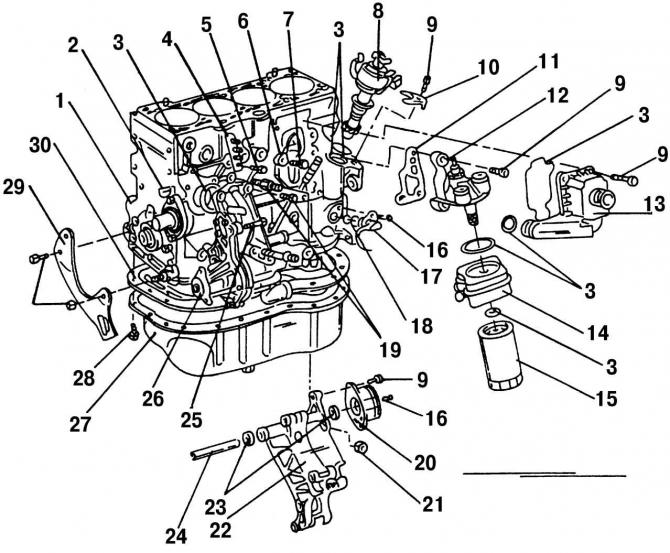
Fig. 135. Front part of the cylinder block with parts installed on it: 1 - cylinder block; 2 - segment key; 3 - O-ring seal; 4 - place of connection of the engine with the "ground"; 5 - bolt, 25 Nm; 6 - knock sensor; 7 - bolt, 20 Nm; 8 - ignition distributor; 9 - bolt, 25 Nm; 10 - terminal; 11 - gasket; 12 - oil filter base; 13 - automatic crankcase ventilation system; 14 - oil radiator; 15 - oil filter; 16 - bolt, 10 Nm; 17 - crankshaft speed sensor; 18 - support rings; 19 - bolt, 20 Nm (tighten another 90°), always replaceable; 20 - elastic clamping element; 21 - nut, 30 Nm; 22 - bracket; 23 - sealing ring; 24 - clamping lever; 25 - T-head bolt; 26 - Cooling system pump; 27 - pallet; 28 - bolt, 20 Nm, internal hexagon; 29 - Power steering pump holder; 30 - gasket (always a replacement)
All instructions and recommendations given for the VR6 engine cylinder block (see subsection 2.5), are also suitable for the 2.0-liter engine. The design of the front part of the cylinder block of the 2.0-liter engine is shown in Fig. 135.
(View the original on this resource www.VWmanual.ru)
Visitor comments