
Since the engine must be completely disassembled, follow these guidelines for completely disassembling the engine:
- remove the gearbox from the engine;
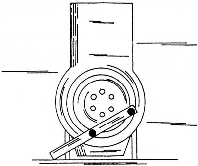
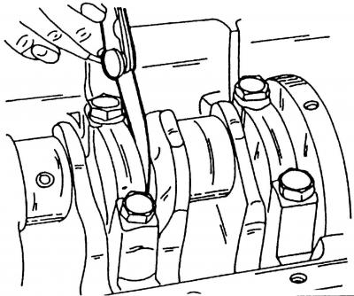
Pic. 70. Blocking with a flywheel lock
- on a car with a manual transmission with a screwdriver inserted into the ring gear of the flywheel, fix the flywheel in a fixed position and unscrew the flywheel mounting bolts. To securely lock the flywheel, you can use the latch (pic. 70), then unscrew the flywheel bolts;
- before removing the flywheel with a punch, mark the relative position of the pressure plate and the flywheel to avoid installation errors;
- unscrew the crankshaft pulley bolt from the front of the engine;
- on a vehicle with an automatic transmission, remove the drive pulley.
- remove the cylinder head (see point 3.3.1) together with the intake and exhaust manifold;
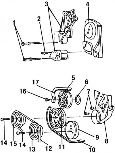
Pic. 106. Details of the timing mechanism drive: 1 - bolts, 55 Nm; 2 - bolt, 20 Nm; 3 - engine mount clamp; 4 - upper part of the protective cover; 5 - tensioner roller; 6 - dust cap; 7 - bolts, 10 Nm; 8 - lower part of the protective cover; 9 - pulley for the drive of the cooling system pump; 10 - V-ribbed belt; 11 - flywheel; 12 - V-belt; 13 - pulley of the pump of the cooling system; 14 - bolt, 25 Nm; 15 - crankshaft pulley; 16 - bolt, 25 Nm; 17 - poly V-belt tensioner lever
- unscrew the fastening bolt 14 (pic. 106) and remove the pulley 13 of the coolant pump and the lower protective cover 8 of the toothed drive belt;
- mark (preferably in color) on the outer side of the toothed drive belt, its direction of rotation;
- loosen the belt tensioner nuts and remove the toothed drive belt from the pulleys and from the tensioner;
Attention! After removing the toothed drive belt, the camshaft must not be rotated.
- unscrew the mounting bolts and remove the oil pan (see subsection 4.1);
- remove the oil pump (see point 4.2.1);
- if only the crankshaft is to be removed, the pistons and connecting rods may remain inside the cylinder block. In this case, mark and remove the connecting rod bearing caps in turn and leave them assembled with the liners. Otherwise, remove the pistons and connecting rods (see point 2.4.1). Please note that the used «malleable screws» should always be changed;
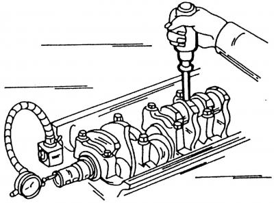
Pic. 80. Checking the axial free play of the crankshaft using a measuring device
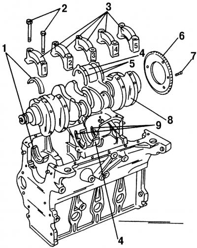
Pic. 104. Disassembled cylinder block: 1 - bearing shell No. 1, 2, 4 and 5; 2 - cover bolts; 3 - bearing caps; 4 - bearing shell No. 3; 5 - thrust semi-ring on the bearing cover; 6 - gear rim of the crankshaft speed sensor; 7 - bolt, 10 Nm (turn another 90°); 8 - crankshaft; 9 - thrust half rings of the cylinder block
- measure the axial free play of the crankshaft. To do this, install a rack with an indicator on the front of the cylinder block so that the indicator foot rests against the flange of the front end of the crankshaft (pic. 80). Use a screwdriver to move the crankshaft to the side and set the device to zero, after which, move the shaft to the other side. The arrow of the device will show the axial free play of the shaft, which should be no more than 0.25 mm. If the stroke is greater, then this should be taken into account during assembly and brought back to normal by replacing the old half-rings with new ones or by installing half-rings of increased thickness. Earbuds 4 (pic. 104) bearings No. 3 have two upper 5 and two lower 9 thrust half rings, which regulate the axial free play of the crankshaft;
Pic. 81. Measurement of the axial free play of the crankshaft with a feeler gauge
- if a measuring device is not available, the axial play can be measured with a feeler gauge (pic. 81), on the middle bearing, between the connecting rod bearing flange, where the thrust half rings are located, and the surface of the crankshaft;
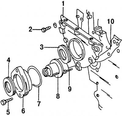
Pic. 136. Individual elements of the front of the cylinder block: 1 - stuffing box cover; 2 - bolt, 20 Nm; 3 - front crankshaft oil seal; 4 - an epiploon of an intermediate shaft; 5 - bolt, 25 Nm; 6 - cover of the gland of the intermediate shaft; 7 - O-shaped sealing ring; 8 - intermediate shaft; 9 - bolt, 10 Nm; 10 - gasket
- unscrew bolts 2 (pic. 136) fasteners and remove cover 1 at the front of the engine. There is an o-ring in the flange, which should be knocked out immediately, as it needs to be replaced;
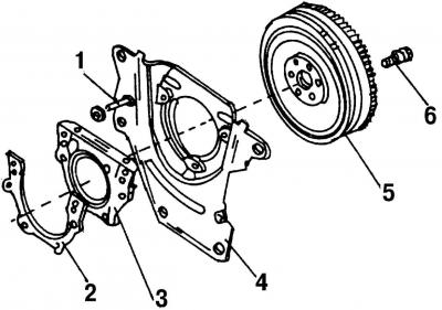
Pic. 137. Individual elements of the rear of the cylinder block: 1 - locating pin; 2 - gasket; 3 - cover; 4 - intermediate plate of the engine; 5 - flywheel; 6 - bolt, 60 Nm (turn another 90°), always a substitute
- remove intermediate plate 4 (pic. 137) engine. The plate is guided by dowel pins;
- unscrew the bolts of the flange cover and remove the flange with the sealing ring. The sealing ring can be immediately knocked out, as it should always be changed;
- Loosen bolts 2 gradually in a diagonal pattern (pic. 104) caps 3 of the crankshaft bearings 8, and remove them one by one. Check that the caps are labeled with the correct numbers. Carry out the numbering of the bearing caps from the side of the drive pulley of the engine units;
- remove the main journal bearing shells and place them together with the corresponding bearing caps. The lower bearing shells of the crankshaft do not have a groove on the inner surface. No adjustments can be made on them. In case of scuffing, risks or delaminations, replace the liners with new ones;
- mark (preferably in color) the back sides of each insert;
- remove from the middle bearing of the crankshaft two upper thrust half rings 5 (pic. 104). They should also be marked so that they can be correctly installed during assembly;
- remove the crankshaft from the bearing seats;
- remove the remaining liners from the engine crankcase and put them together with other liners and covers;
- remove the lower thrust half rings 9 from the middle bearing.
Visitor comments