
Attention! Do not, under any circumstances, remove the cylinder head when the engine temperature is above 40°C, as this may cause deformation of the cylinder head.
Note. If the car is equipped with an anti-theft system with a security code, then you must have the code with you in order to turn on the system after connecting the battery.
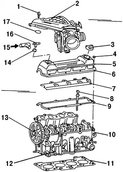
Pic. 105. Details of the upper part of the cylinder head: 1 - bolt, 16 Nm; 2 - central cover (above the top of the intake manifold); 3 - oil filler cap; 4 - nut, 10 Nm; 5 - stiffener; 6 - cylinder head cover; 7 - oil deflector; 8 - a bolt of fastening of a head of the block of cylinders; 9 - cylinder head cover gasket; 10 - cylinder head; 11 - cylinder head gasket; 12 - lifting eye; 13 - camshaft gear; 14 - plug; 15 - from the crankcase ventilation system; 16 - T-shaped fitting; 17 - O-ring (always a substitute)
The parts that need to be removed in order to dismantle the cylinder head from the cylinder block are shown in fig. 105.
Remove the cylinder head in the following order:
- disconnect the terminal «–» from AB by unscrewing the corresponding bolt and nut;
Attention! In order to avoid damage to the computer, it is necessary to disconnect the battery terminals only when the ignition is off.
Attention! When the battery is disconnected, all recorded codes in the memory device are erased.
- drain the coolant from the cooling system (clause 5.1.1);
- remove the upper part of the intake manifold;
- disconnect the upper coolant hose from the radiator to the pipe;
- disconnect all electrical wires from the cylinder head;
- disconnect the fuel lines, throttle cable and brake booster vacuum hose;
Attention! The fuel lines are under pressure. Before disconnecting the fuel hose from its mount, grasp the fuel hose connection with a thick rag and, carefully pulling it off the mount, relieve pressure in the system.
- mark and disconnect all pipes, electrical wires, hoses, connections, etc. between the cylinder head and the body;
- remove cover 6 (pic. 105) cylinder heads with gasket;
- remove the oil deflector 7 (pic. 105) and two reinforcements located on the sides of the cylinder head cover;
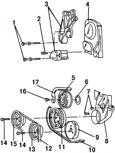
Pic. 106. Details of the timing mechanism drive: 1 - bolts, 55 Nm; 2 - bolt, 20 Nm; 3 - engine mount clamp; 4 - upper part of the protective cover; 5 - tensioner roller; 6 - dust cap; 7 - bolts, 10 Nm; 8 - lower part of the protective cover; 9 - pulley for the drive of the cooling system pump; 10 - V-ribbed belt; 11 - flywheel; 12 - V-belt; 13 - pulley of the pump of the cooling system; 14 - bolt, 25 Nm; 15 - crankshaft pulley; 16 - bolt, 25 Nm; 17 - poly V-belt tensioner lever
- remove the top protective cover 4 (pic. 106) toothed drive belt;
- unscrew the nut securing the tension mechanism, loosen the toothed drive belt (see subsection 3.7) and carefully remove it from the camshaft pulley. At the same time, keep the belt tight, and tie it in the appropriate way so that it does not slip off the crankshaft pulley. But don't tie it too tight at the same time;
- unscrew the rear protective cover of the toothed belt located behind the toothed belt from the cylinder head;
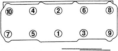
Pic. 107. The sequence of tightening the cylinder head bolts. Unscrewing the bolts is carried out in reverse order
- unscrew in several steps in the reverse order shown in fig. 107, cylinder head bolts, remove the bolts and remove the cylinder head with gasket.
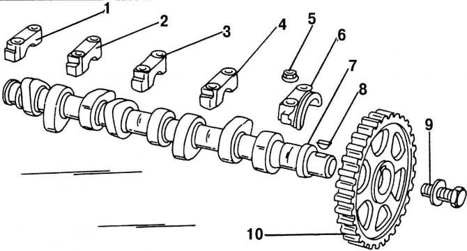
Pic. 108. Details of the camshaft: 1 - bearing cover No. 5; 2 - bearing cover No. 4; 3 - bearing cap No. 3; 4 - bearing cover No. 2; 5 - nut, 20 Nm; 6 - bearing cover No. 1; 7 - camshaft; 8 - segment key; 9 - bolt with washer, 80 Nm; 10 - camshaft gear
Camshaft 7 (pic. 108) can also be removed from the engine installed on the car (see point 3.3.3).
Visitor comments