
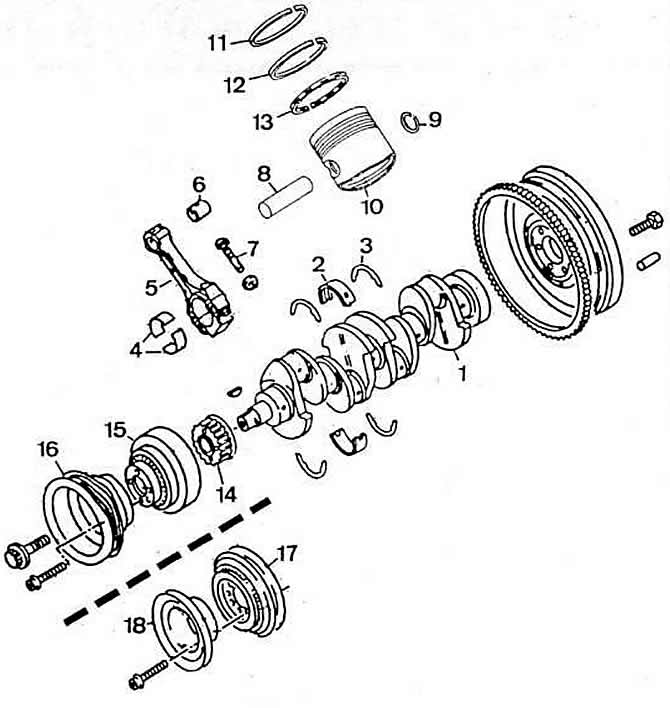
Pic. 2-139. Details of the crank mechanism:
1 - crankshaft;
2 - insert of the main bearing of the crankshaft;
3 - persistent half ring;
4 - connecting rod bearing shells;
5 - connecting rod;
6 - bushing of the upper head of the connecting rod;
7 — a bolt of a cover of a rod;
8 - piston pin;
9 — a lock ring of a piston pin;
10 - piston;
11 - top compression ring;
12 - lower compression ring;
13 - oil scraper ring;
14 - toothed pulley of the crankshaft;
15 - torsional vibration damper;
16 - crankshaft pulley;
17 - crankshaft pulley with a torsional vibration damper on vehicles with air conditioning or power steering;
18 - crankshaft pulley on vehicles with air conditioning and power steering.
The crankshaft is steel, forged, five-bearing, with four counterweights.
Main journals diameter, mm:
- nominal: 54.00-0,022-0,042
- 1st repair size: 53.75-0,022-0,042
- 2nd repair size: 53.50-0,022-0,042
- 3rd repair size: 53.25-0,022-0,042
The maximum admissible ovality of necks, no more, mm: 0,003.
Diameter of connecting rod journals, mm:
- nominal: 47.80-0,022-0,042
- 1st repair size: 47.55-0,022-0,042
- 2nd repair size: 47.30-0,022-0,042
- 3rd repair size: 47.05-0,022-0,042
Axial clearance of the crankshaft when measured on the middle support, mm:
- nominal: 0.07-0.17;
- maximum allowable: 0.25.
Gap between liners and main journals of the crankshaft, mm:
- nominal: 0.03-0.08 (0,02-0,06);
- maximum allowable (in operation): 0,17.
The flywheel is attached to the crankshaft flange with six bolts.
Permissible axial runout of the flywheel when measured along the circumference of the contact surface with the clutch driven disk, not more than, mm: 0.08.
The pistons are cast from aluminum alloy and have a flat bottom. Four recesses are made on the bottom of each piston, which prevent contact (blows) about the bottom of the piston of the valve plates in case of violation of the gas distribution headlights. To reduce the temperature of the piston head and the area of the upper compression ring, the inner surface of the bottom is cooled by an oil jet directed through a special fixed nozzle installed in the crankcase.
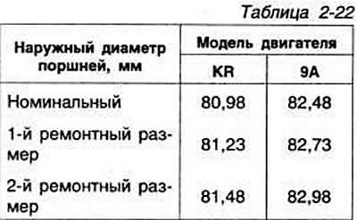
Piston outer diameters are shown in Table 2-22.
The piston diameter is measured at a distance of 10 mm from the lower edge of the piston skirt at an angle of 90°to the axis of the piston pin. The deviation of the piston diameter from the nominal or repair size should not exceed 0.04 mm.
The piston pins are floating. From axial displacement, they are held by two retaining rings.
Three rings are installed on each piston: two compression and one oil scraper.
The gap in the lock is 0.20-0.40 mm for the upper and lower compression rings; oil scraper ring 0.25-0.50 mm. The maximum allowable clearance for wear is 1.0 mm.
The gap between the ring and the piston groove is 0.02-0.07 mm for the upper compression ring; lower compression ring 0.02-0.06 mm. The maximum allowable clearance for wear is 0.15 mm.
The gap in the lock is measured on the ring installed in the cylinder at a distance of 15 mm from the lower edge of the cylinder. Connecting rods are steel, forged, with an I-section rod, with thin-walled liners. A bushing is pressed into the upper head of the connecting rod. A cap of the lower head of a connecting rod of direct section.
When installing the connecting rod and piston group, the side of the connecting rod with the mark «IN» must face towards the camshaft drive.
Axial clearance of the connecting rod on the crankshaft journal:
- nominal 0.05-0.31 mm;
- maximum 0.37 mm.
Clearance in operation between the liners and the crankshaft journals:
- nominal 0.01-0.06 mm;
- maximum allowable 0.12 mm.
The clearance between the piston pin and the bushing of the upper head of the connecting rod is 0.003-0.007 mm.
Visitor comments