
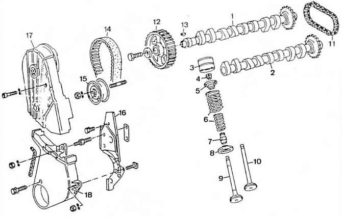
Pic. 2-140. Timing mechanism details:
1 - exhaust camshaft;
2 - intake camshaft;
3 - hydraulic pusher;
4 - crackers;
5 — a plate of valve springs;
6 - valve springs;
7 - oil cap;
8 - support washer valve springs;
9 - exhaust valve;
10 - inlet valve;
11 - intake camshaft drive circuit;
12 — a gear pulley of a final camshaft;
13 - key;
14 - toothed belt drive camshafts;
15 - tension roller;
16 — a back protective cover of a gear belt;
17 - upper front protective cover of the toothed belt;
18 - lower front protective cover of the toothed belt.
The toothed pulleys of the camshaft and crankshaft are fastened with segment keys.
An intermediate shaft with a toothed pulley is installed in the cylinder block, which drives the oil pump and ignition distributor. The intermediate shaft is driven by the exhaust camshaft timing belt.
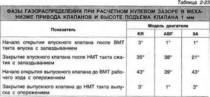
The valve timing at the calculated zero clearance in the valve drive mechanism and the valve lift of 1 mm are presented in Table 2-23.
The engine uses two separate intake and exhaust valve drives with intake and exhaust camshafts. The maximum axial movement of the camshafts is 0.15 mm. The gap between the necks of the shaft and the holes of the supports is not more than 0.1 mm.
The maximum allowable ovality of the shaft necks is not more than 0.01 mm.
The intake camshaft has an alphanumeric marking applied between the intake cams of the 3rd and 4th cylinders:
- engine «KR»: 027 101 K or L;
- engine «9A»: 027 101 M or N.
Engine camshafts «ABF» have the following marking applied between the cams of the 1st and 2nd cylinders:
- intake shaft: 051 102;
- exhaust shaft: 051 101 or 051 101 A.
The intermediate shaft is driven by the exhaust camshaft timing belt. The intermediate shaft drives the oil pump and ignition distributor. The axial clearance of the intermediate shaft is not more than 0.25 mm.
Visitor comments