
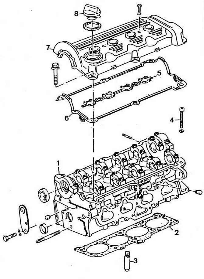
Pic. 2-141. Cylinder Head Details:
1 - cylinder head;
2 - cylinder head gasket;
3 - valve guide sleeve;
4 — a bolt of fastening of a head of cylinders;
5, 6 - cylinder head cover gasket;
7 - cylinder head cover;
8 - oil filler plug.
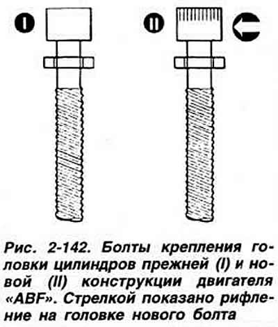
The cylinder head gasket is installed with a label «Oben» («Top») up Since February 1994 on the engine «ABF» a new metal cylinder head gasket is installed, which required the use of special cylinder head bolts. When repairing the engine, it is allowed to install a new cylinder head gasket on engines of previous releases, provided that the indicated new cylinder head bolts are used.
The bolts used with the old cylinder head gasket have a smooth head end, while the new bolts have a knurled head (pic. 2-142). The order and tightening torque of the cylinder head bolts remained unchanged.
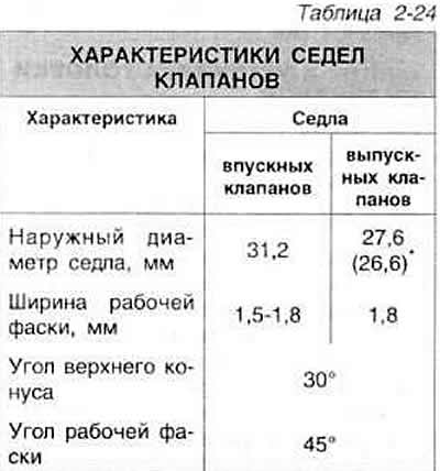
Valve seats
The valve seats are made of special steel and pressed into the cylinder head. Valve seats must only be replaced at a workshop. If signs of burning or wear appear on the valve seats, which cannot be removed if the required angles and width of the working chamfers are observed, the cylinder head as a whole must be replaced.
Note. Grinding of valve seats is done only to obtain the desired surface quality. Before grinding, determine the maximum allowable grinding size (distance from the end of the valve stem to the mating surface of the cylinder head). With a decrease in the specified size, automatic compensation of gaps in the valve drive mechanism by hydraulic tappets is not provided. In this case, the cylinder head must be replaced.
Brackets for engine «ABF».
The valve guides are made of special bronze and pressed into the cylinder head. Maximum allowable clearance (when worn) between valve stem and guide bush (the measurement technique is described in section «8-valve engines»): for intake valves 1.0 mm; for exhaust valves 1.3 mm.
The length of the guide bushings is 38 mm.
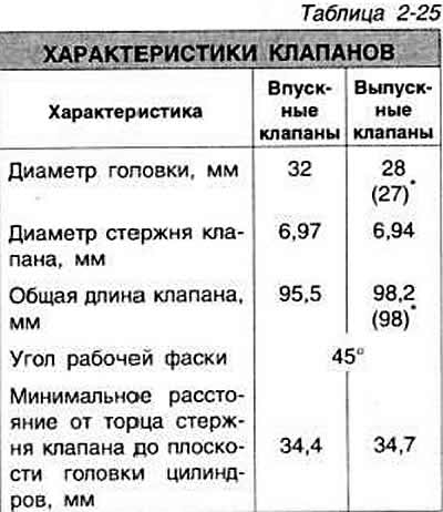
Valves are made of special steel. To improve heat transfer, exhaust valves have an internal closed cavity filled with sodium in a certain proportion. The exhaust valves are arranged vertically in a row, the intake valves are arranged obliquely at an angle of 25°to the cylinder axis.
Brackets for engine «ABF».
The gaps in the valve drive mechanism are compensated automatically by hydraulic tappets.
Each intake and exhaust valve has two springs. The intake and exhaust valve springs are the same. Hydraulic tappets are installed directly in the cylinder head. The valves are driven by camshaft cams through hydraulic tappet plungers. The free travel of the pusher plungers is not more than 0.1 mm.
Visitor comments