



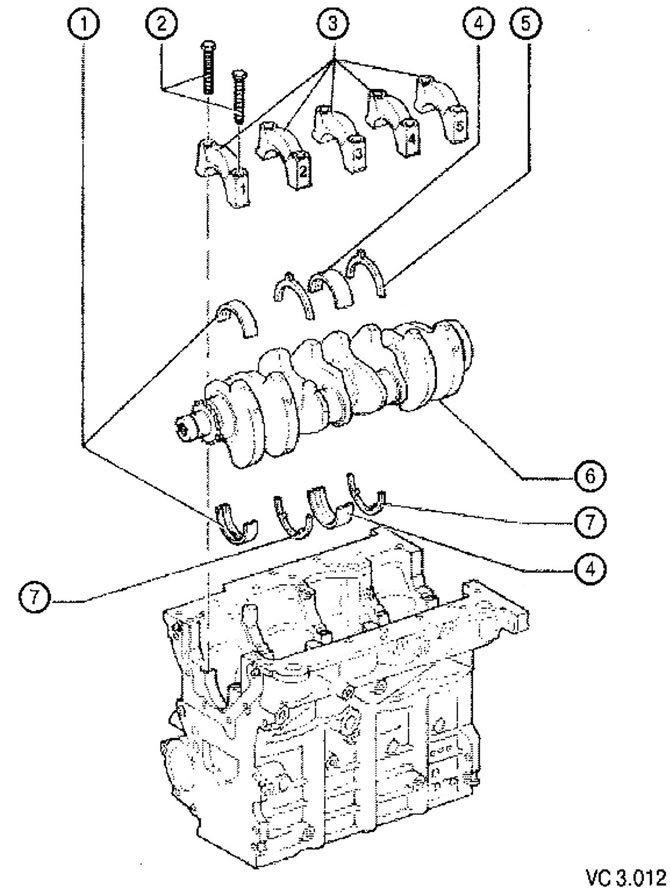
List of crank mechanism parts with technological notes on repairs to figure VC3.012:
1. Inserts 1, 2, 4 and 5:
- without a lubrication groove, installed in main bearing caps;
- with a lubrication groove, installed in the cylinder block;
- do not swap previously used liners (mark when removed).
2. Main bearing cap mounting screws: 65 Nm and tighten by 1/4 turn (90°):
- replace with new ones during assembly;
- to measure the radial clearance, tighten to a torque of 65 Nm, without tightening by 90°.
3. Bearing cover:
- bearing cap 1: counting from the timing drive;
- bearing cover 3: with recesses for thrust half rings;
- the retaining protrusions of the liners installed in the cylinder block and in the main bearing caps must be installed opposite each other.
4. Insert 3:
- without a lubrication groove, installed in main bearing caps;
- with a lubrication groove is installed in the cylinder block,
5. Thrust half ring installed in the main bearing cap 3:
- When installing, make sure it is securely fixed in the seat.
6. Crankshaft:
- axial run-up:
- new shaft: 0.07...0.17 mm,
- wear limit: 0.37 mm;
- measure the radial clearance using a Plastigage plastic gauge:
- new shaft: 0.03...0.08 mm,
- wear limit: 0.17 mm;
- when measuring the radial clearance, do not rotate the crankshaft.
7. Thrust half ring installed in the cylinder block (main bearing 3).
Crankshaft dimensions
| Nominal size | Main journal diameter | Crankpin diameter |
| The meaning of size | 54,00 (0,022; -0.042) mm | 47,80 (-0,022; -0.042) mm |
Visitor comments