
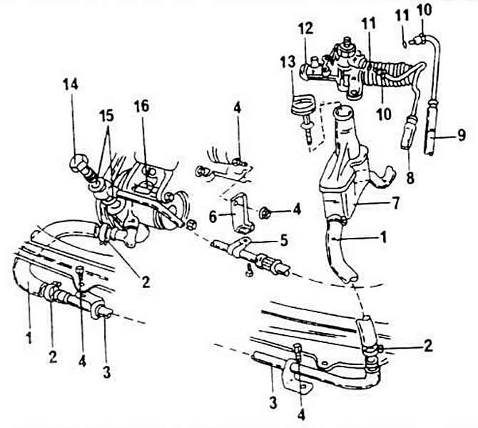
How to mount the power steering mechanism, reserve tank, hydraulic pipes and hose connections:
1 - inlet hose
2 - hose clamp
3 - tube of the cooling system
4 - bolt, tightened with a tightening torque of 10 Nm
5 - tube attachment device
6 - corner
7 - spare tank
8 - drain hose
9 - pressure line, tightened with a tightening torque of 30 Nm
10 - union nut, tightened with a tightening torque of 30 Nm
11 - sealing O-ring, always replaced with a new one
12 - power steering mechanism
13 - stopper of an oil measuring ruler
14 - hollow bolt, tightened with a tightening torque of 30 Nm
15 - seal, always replaced with a new one
16 - auxiliary pump of the steering mechanism
The pump cannot be repaired and, in the event of a malfunction, is replaced with a new one.
The liquid level gauge is located on the stopper of the reserve tank. The measuring ruler is marked «Min» and «max», through which the liquid level in the system can be determined.
Hollow bolts are sealed on each side with washers. If one of the ring connectors is unscrewed, the washers are always replaced with new ones.
The same applies to the O-ring that is located in the hole for connecting the drain line.
Visitor comments