
Disassembly
Remove engine.
Remove the exhaust system.
Remove intake manifold with carburetor.
Remove water pump with water hoses.
Remove oil filter.
Remove the ignition distributor and the ignition distributor drive shaft.
Remove fuel pump.
Remove clutch.
Remove flywheel.
Remove generator.
Remove the hydraulic oil switch and intake screen.
Remove oil pump.
Remove cylinder heads.
Remove, mark and fold the hydraulic tappets in the correct order.
Remove cylinders and pistons.
Loosen the crankcase nuts with a wrench.
Loosen the fastening of the right half of the crankcase with light blows of a rubber mallet and remove it. Never use a screwdriver or similar accessory to loosen the fastening. Because of this, contact surfaces can be damaged, which will disable the crankcase.
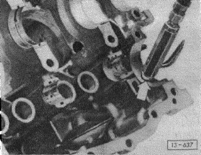
When removing the right half, make sure that the connecting rods do not tip over to the side and do not damage the contact surface of the left half of the crankcase.
Remove crankshaft and camshaft.
Remove intake pipe with mesh.
Attention: Mark the installation position of the bearing shells. When removing crankshaft and camshaft, ensure that all camshaft bearings and crankshaft bearing 2 separate.
After marking, remove all camshaft bearings and crankshaft bearing 2.
Remove the oil pressure control valve.
Examination
Wash the contact surfaces of both halves of the crankcase with gasoline or acetone without damaging the metal surface.
Carefully check the integrity and absence of cracks on the crankcase halves. 4
Check the tightness of the studs. With tapped holes, Heli-Coli inserts can be installed.
Assembly
Before assembling the crankcase halves, blow out the intake pipe with the screen with compressed air.
If it is necessary to replace the inlet pipe with a mesh, unscrew the bolt and pull the pipe out of the crankcase.
Attention: Both halves of the crankcase were machined bonded during manufacture. Therefore, they should only be replaced together.
Note: Crankcases for 1.9 l engines up to 11.85 are no longer available. Instead, a new single crankcase should be installed (for engines with a working volume of 1.9 l and 2.1 l). At the same time, they are replaced by parts of a new type: new crankshaft bearing shells 1, 2 and 3, as well as bearing accelerating washer 1, see also section "Installing the crankshaft". On some models of engines with a fuel injection device, a new intake manifold must also be installed, obtain information from a service station.
Thoroughly wash the halves of the crankcase with gasoline and blow out the lubrication channels with compressed air.
Clamp the left half of the crankcase up.
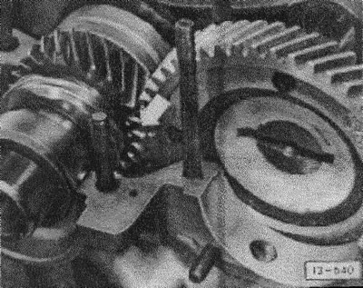
With the correct installation of the crankshaft and camshaft, the mark on the camshaft is located between the marks (arrow) on the crankshaft. Pay attention to the secure fit of the crankshaft bearing pins.
Lubricate the crankshaft and camshaft bearing shells with engine oil and insert in accordance with the markings. The projections of the camshaft bearing shells must fit into the recesses in the engine crankcase.
Insert crankshaft and camshaft. At the same time, observe the marking.
Attention: number "0" not to be confused with letter "ABOUT", which serves when installing the gears of the gas distribution mechanism drive. There are no markings for the crankshaft gears.
Coat the contact surfaces of the engine crankcase halves with an even thin layer of VAG AMV 188 02 sealing compound. Clean and degrease these contact surfaces beforehand. The sealing compound must never get into the lubrication channels of the crankshaft and camshaft bearings.
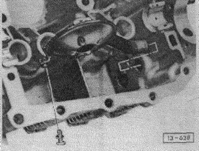
Insert the camshaft cover covered with sealing compound with the bottom facing out.
Connect both halves of the engine crankcase.
Before installation, apply KZ glue on both sides of all gasket washers installed under the nuts of the engine crankcase halves.
The nut must first be tightened to 20 Nm (M8, 13 mm), which is next to the pin (M10) bearing 1 crankshaft. Only then can the remaining M10 nuts be tightened to a torque of 35 Nm. Then tighten the rest of the M8 nuts to a torque of 20 Nm.
Caution: Be sure to follow the tightening sequence.
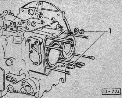
When assembling the crankcase halves, the tightening torque of both M10 nuts -1- is 45 Nm from the following engine numbers:
- DF 035607
- DG 064473
- GW 000337
- MV, DJ: everything.
On older engines (e.g. GW engine up to part number 000336) these nuts are tightened with a torque of 35 Nm.
Caution: Failure to follow this instruction will result in engine damage.
Check the ease of rotation of the crankshaft.
Assemble the engine.
Visitor comments