
English Русский
Български
Беларускі
Український
Српски
Hrvatski
Română
Polski
Slovenský
Magyar
  |  Articles  |  Sitemap  |  Contacts  |    |
Car maintenance Ford Car maintenance Hyundai Car maintenance Chevrolet Car maintenance BMW Car maintenance Audi Car maintenance Opel Car maintenance AvtoVAZ
VWmanual.ru


Main   Passat   Golf   Polo   Touareg   Tiguan   Sharan   Transporter   Others  
Golf 1 (1974-1984, diesel) Golf 1 (1974-1984, petrol) Golf 2 (1984-1993, petrol) Golf 2 (1984-1993) Golf 3 (1991-1997) Golf 4 (1997-2004) Golf 5 (2003-2008)

Disassembly and assembly of the engine (VW Golf 3)

  • Main
  • Golf
  • Golf 3
  • Petrol engine
  • Engine repair
  • Disassembly and assembly of the engine
            0


Contents: Disassembly ↓ Assembly ↓

Disassembly
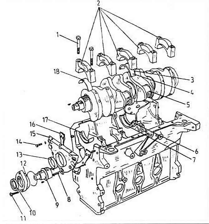


1 - main bearing cap screw

1 - main bearing cap screw
2 - main bearing caps
3 - upper starting half washers
4 - upper main bearing shells
5 - crankshaft
6 - lower main bearing shells
7 - lower thrust washers
8 - screw, 10 Nm
9 - intermediate shaft
10 - oil seal ring
11 - screw, 25 Nm
12 - flange for intermediate shaft
13 - oil seal ring
14 - screw, 20 Nm
15 - Front flange of the sealing ring
16 - seal
17 - lower bearing shell
18 - upper bearing shell


Before starting work, you need to thoroughly clean the entire outer surface of the engine. Cover all engine openings with a clean cloth beforehand to prevent foreign objects from getting inside.

Engine disassembly is described in detail below. Therefore, we describe the work that is carried out either with the engine assembled or disassembled, without repeating specific disassembly operations.

If it is necessary to completely disassemble the engine, it is only necessary to combine individual operations with each other, and in the specified sequence.

Generally, when disassembling, it is important to note the position of all moving or sliding parts before disassembling, so that they can be reinstalled in their original position if they are to be used again. This is especially important for pistons, valves, bearing caps and bearing shells.
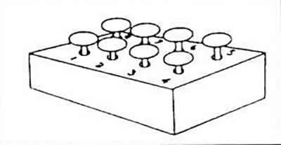


Generally, when disassembling, it is important to note the position of all moving or sliding parts…


Don't mix up the parts. The flaps can be stuck into the bottom of an upturned cardboard box so that they can be numbered.

Bearing and seal surfaces should never be marked with a scriber or even a number stamp. Many parts are made of aluminum and must be handled accordingly. If some parts can only be separated by tapping, use only a rubber, plastic, or leather mallet.

If you do not have the installation diagram according to the instructions, it is best to cut out suitable wooden parts on which the engine can be placed in such a way that the upper and lower sides of the engine can be accessed. After dismantling, the cylinder head can be clamped in a vice together with the metal bracket into which the studs of the intake duct are screwed.

The following is a typical engine disassembly.

Remove all minor engine components, i.e. distributor, carburetor with intake manifold, exhaust manifold, injection system components, etc.

Unscrew the control belt protection device and remove it.

Remove the belt tensioner from the end of the engine.

Unscrew the crankshaft belt pulley together with the flywheel from the shaft.


Unscrew the water pump.

Unscrew the oil filters. Unscrew the oil cooler. placed between the oil filter and the filter base (remove the nut).

If necessary, unscrew the base from the engine.

Remove the dipstick.

Unscrew the cylinder head cover and immediately remove the seal.

Remove the cylinder head.

Turn the engine over and unscrew the oil pan. Remove the seal.

Unscrew the oil pump from the bottom of the crankcase and remove it.

Mark the cylinder numbers on the connecting rod bearing caps with paint and remove the bearing caps one by one. The two connecting rod bearings must always be at bottom dead center when the caps are disconnected. Pull the connecting rods up out of the cylinder bores one by one together with the pistons. Note that the caps and bearing shells are immediately screwed back onto the corresponding connecting rods. The connecting rod bearings are fastened with flexible screws; the screws cannot be reused.

Remove the crankshaft. In this case, mark the bearing caps with numbers (No. 1 on the belt pulley side, No.5 on the flywheel side).

Remove the intermediate shaft flywheel.

Unscrew the intermediate shaft flange and press the flange. Remove the shaft from the engine.

Assembly


When carrying out any engine assembly operation, the following provisions must be followed.

Check for foreign bodies before assembly.

Apply an oil lubricating film to all rotating or sliding parts. Do this before assembly, otherwise the oil cannot reach the bearing surfaces themselves, it is especially important to generously lubricate the pistons, piston rings and cylinder walls with machine oil before assembly.

Thoroughly clean all cylinder block parts if the engine is completely disassembled. When partially disassembling the engine, make sure that no foreign object can get into the disassembled parts of the engine or its cavities. Either seal or plug all openings with rags.

It is best to blow out the oil channels and holes with compressed air. If this is not possible, push the channels or holes with a suitable wooden object (under no circumstances metallic).

Always replace sealing rings, gaskets, etc. You cannot save on such parts and use previously damaged parts.

The table of dimensions and adjustment parameters indicates the wear limits of most moving parts. If any part is in doubt or is close to the wear limit, it is better to replace the part to avoid disassembling the mechanism again in the near future.

This article is available at russian, bulgarian, belarusian, ukrainian, serbian, croatian, romanian, polish, slovak, hungarian
The text has been checked: Medvedeva Elena

Share information:

Previous articles
Alignment of the engine and gearbox
Separation of engine and gearbox
Removal and installation the engine
Tightening torques for engine threaded connections
Technical parameters of the gasoline engine
Engine with a working volume of 2.0 liters
Next articles
Cylinder head and valves
Removal the cylinder head
Disassembling the cylinder head
Cylinder head valve springs
Cylinder head valve seats
Cylinder head valves


Similar articles from other manuals for VW cars:
Starting the car engine Passat B3 (1988-1993)
Starting the engine from an auxiliary battery Polo 3 (1995-2003)
Car engine number Touareg 1 (2002-2006)
Car engine number Tiguan 1 (2007-2015)
Checking the engine oil level and replacing it Sharan 1 (1995-2000)
Starting the engine from another source Transporter T4 (1990-2003)
Visual inspection of parts in the engine compartment and on the… Caddy 3 (2003-2010)
Link to this page in different formats


Visitor comments


No comments yet


How much will 13 + 36 =


Golf 5 
  • General information
  • User manual
  • Maintenance
  • Troubleshooting
  • Power unit
  • Engine repair
  • Cooling and ventilation system
  • Fuel system
  • Ignition system
  • Transmission
  • Clutch
  • Mechanical gearbox
  • Automatic gearbox
  • Chassis
  • Brake system
  • Car suspension
  • Steering
  • Body
  • Interior (internal elements)
  • Exterior (external elements)
  • Doors and covers
  • Electrical equipment
  • Power devices
  • Washers and wipers
  • Lighting and appliances
  • Electrical circuits
Golf 4 
  • General information
  • User manual
  • Weekly checks
  • Maintenance
  • Power unit
  • Petrol engines
  • Diesel engines
  • Cooling system
  • Fuel system (petrol)
  • Control system (petrol)
  • Fuel system (diesel)
  • Exhaust system
  • Transmission
  • Clutch
  • Car gearbox
  • Drive shafts
  • Chassis
  • Car suspension
  • Steering
  • Wheels and tires
  • Brake system
  • Body
  • Exterior (external elements)
  • Interior (internal elements)
  • Ventilation and heating
  • Car doors and sunroof
  • Washers and glass cleaners
  • Electrical equipment
  • Power devices
  • Lighting and appliances
  • Electrical circuits
Golf 3 
  • Petrol engine
  • Engine repair
  • Lubrication system
  • Cooling system
  • Ignition system
  • Diesel engine
  • Engine repair
  • Diesel injection system
  • Pre-glow system
  • Transmission
  • Clutch
  • Gearbox and drive shafts
  • Chassis
  • Steering
  • Wheels and suspension
  • Brake system
  • Electrical equipment
  • Lighting and appliances
  • Electrical circuits
Golf 2 
  • General information
  • Introduction to guide
  • User manual
  • Petrol engines 1.3 l
  • Engine repair
  • Lubrication system
  • Cooling system
  • Carburetors
  • Supply system
  • Ignition system
  • Petrol engines 1.6/1.8 l
  • Engine repair
  • Supply system
  • Ignition system
  • Diesel engines
  • Engine repair
  • Lubrication system
  • Cooling system
  • Power and exhaust system
  • Transmission
  • Clutch
  • 4-speed gearbox 084
  • 5-speed gearbox 085
  • 4-speed gearbox 020/4R
  • 5-speed gearbox 020/4T
  • Automatic gearbox
  • Drive shafts
  • Chassis
  • Steering
  • Car suspension
  • Brake system
  • Body
  • Body elements
  • Doors, locks and windows
  • Electrical equipment
  • Equipment and devices
  • Power devices
Golf 2 (petrol) 
  • General information
  • Characteristics
  • Car care
  • Maintenance
  • Power unit
  • Engine repair
  • Engine 1.05/1.30
  • Engine 1.60/1.80
  • Cooling and lubrication system
  • Power and exhaust system
  • Transmission
  • Clutch
  • Car gearbox
  • Drive shafts
  • Chassis
  • Brake system
  • Steering
  • Suspension
  • Body
  • Body and equipment
  • Electrical equipment
  • Lighting and appliances
  • Electrical circuits
Golf 1 (petrol) 
  • General information
  • Characteristics
  • User manual
  • Maintenance
  • Power unit
  • Engine adjustment
  • Engine 1.1/1.3
  • Engine 1.5/1.6/1.8
  • Engine electrical equipment
  • Cooling system
  • Fuel system
  • Transmission
  • Clutch and manual gearbox
  • Automatic gearbox
  • Chassis
  • Steering
  • Front suspension
  • Rear suspension
  • Brake system
  • Electrical equipment
  • Lighting and appliances
  • Electrical circuits
  • Body
  • Body and equipment
  • Optional equipment
Golf 1 (diesel) 
  • General information
  • Specifications
  • Maintenance
  • Power unit
  • Engine repair
  • Exhaust and turbocharger
  • Cooling system
  • Fuel system
  • Fuel injection system
  • Transmission
  • Clutch and drive shafts
  • Car gearbox
  • Chassis
  • Suspension and wheels
  • Steering
  • Brake system
  • Wheels and tires
  • Body
  • Heating and ventilation
  • Exterior (external elements)
  • Interior (internal elements)
  • Doors and windows
  • Electrical equipment
  • Equipment and devices
  • Lighting system
  • Power devices
  • Electrical circuits
VWmanual.ru © 2016-2026 | Mobile version | News and articles | Sitemap: EN BG BY UA RS HR RO PL SK HU | Write message | Site search
Passat B2 • Passat B3 • Passat B4 • Passat B5 • Passat B6 • Golf 1, diesel • Golf 1, petrol • Golf 2, petrol • Golf 2 • Golf 3 • Golf 4 • Golf 5 • Polo 3 • Polo 4 • Touareg 1 • Tiguan 1 • Sharan 1 • Transporter T3 • Transporter T4 • LT 28 • LT 2D • Beetle • Caddy 3 •
Our website uses cookies to ensure functionality and convenience.