
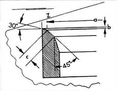
The main parameters of the intake valves:
- a - valve seat diameter, see table of dimensions and adjustment parameters;
- b - maximum processing size;
- c - 1.5-1.8 mm - valve seat width;
- Z - lower edge of the cylinder head;
- 30°- upper correction angle;
- 45°- valve seat angle.
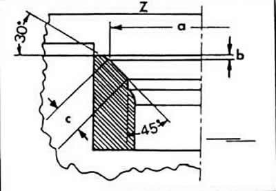
The main parameters of the exhaust valves:
- a - valve seat diameter, see table of dimensions and adjustment parameters;
- b - maximum processing size;
- c - 1.5 mm - valve seat width;
- Z - lower edge of the cylinder head;
- 30°- upper correction angle;
- 45°- valve seat angle.
The following measurements should be taken to determine the amount of additional processing.
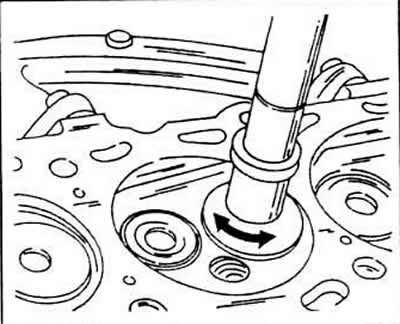
Insert the valve into its guide and press firmly into the seat.
Measure the distance -arrow- (A) between the valve seat and the upper edge of the cylinder head.
Calculate the maximum allowable additional milling dimension of the measured value and the allowable minimum dimension. For a normal head, this size is 34.4mm (for exhaust valves) and 34.7 (for intake valves). If you subtract the minimum distance from the measured value, you get the allowable maximum size (b).
The valve seats must be additionally milled if new valve guides are inserted.
In doing so, they act as follows.
Mill a 45°angle and then use a 30°cutter to lightly machine the top edge of the seat to reduce the width of the valve seat to a size of 1.5-1.8mm (for intake valves) or 1.8 mm (for exhaust valves). Milling should be stopped as soon as the seat width reaches the specified value, now the diameter of the exhaust valve seats is gradually decreasing. when re-milling saddles, pay attention to so as not to violate the radius of this slide.
To avoid too deep penetration of the seat into the cylinder head, the above measurement should be carried out.
Grind reworked valve seats by lubricating the surfaces of the valve seats with grinding paste and inserting the valve into the appropriate seat. Move the blower to the valve and move the valve from side to side.
After grinding, carefully clean all parts from dirt and grinding paste and check the valve seat in the area of the valve disc, as well as the seat ring. Both parts should show a continuous opaque ring defining the width of the valve seat.
With a pencil, apply a few strokes on the valve plate. The strokes should be drawn in a circle at a distance of approximately 1 mm. Then carefully lower the valve into the guide and seat, and then rotate 90°. Lightly press the valve.
Remove the valve and check if the pencil marks are gone from the seat ring. If the valve seat width is within the specified limits, the head can be mounted again. Otherwise, work out the valve seats or, in the worst cases, insert a replacement head.
Visitor comments