



Contents: Removal ↓ Installation ↓
Removal
The engine together with the gearbox is pulled out of the engine compartment forward. Finally, the gearbox can be separated from the engine. Before starting work, it is necessary to familiarize yourself with the following instructions.
The condition for extracting the engine is the use of a powerful lifting mechanism.
The following must be removed: the front part of the car, the fan cover, the shock absorber (push bar) and a refrigeration unit.
If a radio installation is installed, it has an anti-theft device code that must be known before the battery can be disconnected from the power supply.
To avoid damage to the engine electronics control unit, the batteries should only be disconnected when the ignition is switched off. It is also important to wait at least 20 seconds after switching off the ignition before disconnecting the negative battery cable. The so-called "hot wire" in the air flow meter should be burning steadily before the current circuit is interrupted.
Most cables are secured with cable ties and clamps. When removing them, mark their position, and when installing the power unit, re-attach the cable in the same places. Some cable ties have to be cut to release the cable. In such cases, new ties should be used.
If an air conditioner is installed, the cooling circuit must not be opened under any circumstances. This is a job for trained personnel who, using special devices and only in a workshop, are able to reduce the pressure in the air conditioner and reinstall the unit under pressure.
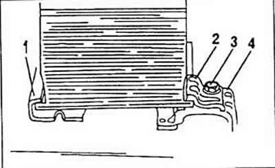
In order to dismantle the power unit with the air conditioner installed, loosen the air compressor and securely tie it to the wall so that the hoses are not under voltage. It is important to take into account that the tubes are very sensitive to bending, so when dismantling this compressor, you must act with special care. The cable connecting the battery to the body should be disconnected taking into account the above instructions (take into account the anti-theft device code for the radio installation), and then remove the battery. The battery is held on the wall by the pressure plate "1" and the bolt "3" as shown in the figure and is supported on the other side by a safety sheet. When installing the battery, the bolt is tightened with a force of 20 Nm.
The engine hood can be unscrewed, although there is no fundamental need for this. If this is done, the outer dimensions of the hinge of the engine hood sheet are outlined with a pencil so that during installation the hood is reinstalled in its original position.
The heating system regulator is set to the "Warm" position.
The locking cap of the cooling system's thermal compensation tank is unscrewed; the engine must remain cold
Remove the air filter completely, together with the connecting elements. Close the openings accordingly so that foreign objects cannot enter the engine.
Move the vehicle either to a pit or a car lift with a platform, or raise the front end far enough on jack stands to allow access to the underside of the body. Be sure to use sturdy jack stands.
Drain the cooling system. The coolant pipe on the top side has a drain plug that can be removed.
Otherwise, release the lower water hose from the nipple and pull it off. The heater control valve must remain open so that all the coolant poured in can flow out of the heater. The coolant contains an antifreeze agent, which should be fished out, if only because it has been present in the system for a long time. To do this, either slightly rotate the coolant pipe to direct the liquid into the reservoir, or place a large flat container under the disconnected radiator hose to catch most of the leaking liquid.
It is preferable to discharge the coolant into an external free space so as not to contaminate the area.
Remove the front part of the body. Be sure to pay attention to the fact that the varnish coating is not damaged during this work.
Loosen the upper water hose clamp and disconnect it from the cylinder head. Also release the hose from the radiator nipple. Secure the hoses with either a spring clamp or clamps with screws. During assembly, spring clamps can be replaced with clamps with screws, since special pliers are required to tighten spring clamps.
Remove the fan casing together with the buffer rod and the radiator. When removing the radiator, the work described below is performed accordingly.
Disconnect the electrical cable from the thermostat switch and from the radiator fan.
Disconnect the cable connector from the rear of the three-phase alternator.
Disconnect the low pressure hoses from the top of the intake manifold.
Unscrew the radiator retaining bracket on the top side.
Remove all remaining coolant hoses (cylinder head radiator, water pump radiator and expansion tank radiator).
Completely release the radiator fasteners and remove it from the engine compartment together with the air intake channel and fan.
Disconnect the 1.8 bar oil pressure cut-off line - this is the switch with the yellow cable. In the same way, disconnect the 0.3 bar oil pressure cut-off line - this is the switch with the blue-black cable.
Disconnect the oil temperature gauge sensor.
Pull the high tension cable out of the center of the ignition distributor.
Pull the connector out of the distributor wall.
Disconnect the electrical leads from the gearbox.
Disconnect the remote thermometer temperature sensor.
Trace all lines between the body and the engine, mark the lines accordingly and disconnect from the engine. Press these lines against the wall so that they do not interfere later.
Unscrew the housing wire from the cylinder head housing.
Disconnect the lines from the starter.
Disconnect the wiring harness from the transmission after releasing the fastener.
Loosen and pull the coolant hoses away from the cylinder head.
Unscrew the receiving cylinder from the gearbox and screw it securely in a hanging position on the chassis accordingly.
Unscrew the flexible jumper from the gearbox.
Disconnect the shift cable from the gearbox. In addition, unscrew the cable holder from the gearbox.
Unscrew and disconnect the tachometer spiral from the gearbox. Close the hole in the gearbox to prevent dirt from getting into it.
Disconnect the throttle cable from the segment actuator and release it from the counter support. Do not pull the retaining clip out of the throttle cable.
Locate the wiring harness in the engine compartment and the large connector separator. (42 connecting contacts).
Disconnect the low pressure hose from the brake booster.
Unscrew the power steering pump from the console and screw it in a hanging position on the engine mount bracket lines.
Remove the spark plug cable guide, spark plug cable and distributor head. This work is described when disassembling the engine. The cover over the cylinder head must also be removed.
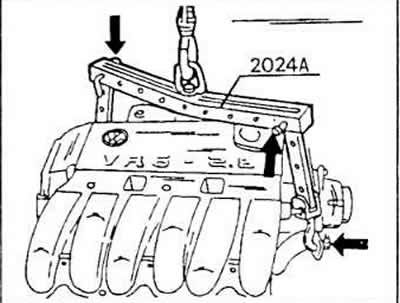
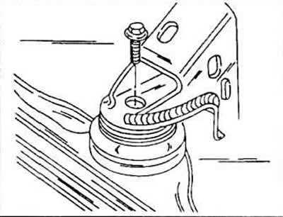
Lift the engine from the hangers using appropriate loops of rope. It is also possible to attach loops of rope to the drive mechanism in a suitable manner. The other end of this rope is fixed to the other side of the cylinder head. This rope is hung on a pulley or a crane and is easily lifted until the rope is taut.
The rubber-metal holder is unscrewed and completely removed.
Both remaining drive mechanism hangers are unscrewed and removed. At the same time, it is checked whether the engine is hanging firmly on the cables.
Release the drive shafts from the flange joints and after release, secure them with wire in a suitable place in a horizontal position on the chassis, to unscrew the bolts, use an insertion nozzle similar to an 8 mm Allen key, without which the bolts can only be removed with great force, especially in cases where they are tightened quite strongly.
Disconnect the outlet pipe connection on the manifold flange and release it from the fastening on the transmission mechanism.
Lift the drive mechanism slightly and rotate it until it can be removed from the engine compartment.
Be careful not to forget any of the terminals and not to leave the engine and gearbox hanging anywhere. This can only be achieved by slowly pulling it out.
Separate the engine from the gearbox.
Installation
The engine is installed in the reverse order, but it is necessary to pay attention to the following points.
Check the condition and replace, if necessary, the clutch release bearing.
Lightly lubricate the clutch release bearing surfaces and wedge engagements with graphite grease. However, do not lubricate the clutch release bearing guide sleeve.
The engine and gearbox are guided by means of matching pins. Before the two parts are assembled, the matching pins must already be in the cylinder block. If they remain in the gearbox during flange removal, they must be transferred to the cylinder block, namely: removed from the gearbox and driven into this block.
Place the engine and gearbox in the correct position. When lowering the drive mechanism, pay attention to "pass" the drive shafts.
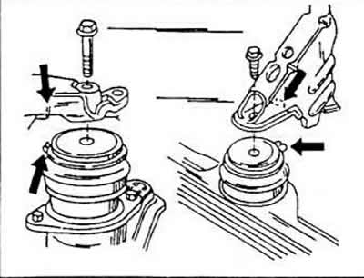
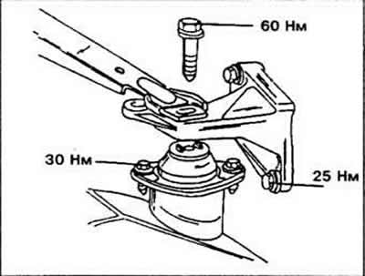
When installing the engine mounts, it is necessary to adhere to the figure. The grooves in the rear right and front engine support brackets must engage with the matching pins in the rubber-metal holders. The engine is therefore first lowered into the mounts before installing the bolts.
First of all, tighten all engine and gearbox mount bolts by hand as tightly as possible by five or six turns.
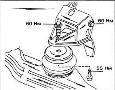
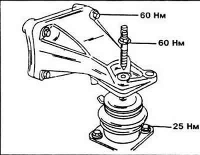
Bleed the engine back and forth thoroughly until the drive train is seated properly before tightening the individual engine and transmission mounts.
Attach the drive shafts and multi-tooth bolts using a special recessed key and tighten them to a tightening torque of 45 Nm.
Attach the exhaust device. Align the main muffler and exhaust pipe and then secure with a rubber ring. If the rubber has stretched, you can bend the mounting hooks on the exhaust device a little. If the tension is too high, the rubber rings will break.
Fill the cooling system if the heater tap is open. Fill the expansion vessel to the mark, and then tighten the plug. Let the engine run for a while to push out all the air. Finally, check the coolant level and make corrections if necessary.
Check the installation of the shift cable. If necessary, make the necessary adjustments or reinstall.
Visitor comments