
Compare the used spring with the new one. To do this, hold both springs in a vise and slowly close the vise. If the compression ratio of both springs is the same - this is a sure sign that they have approximately the same elasticity, if the old spring after compression has become much shorter than the new one - this is a sign of spring fatigue, so the old springs need to be replaced as a set.
Alternately place the springs on a smooth surface (glass plate) so that the closing winding is at the bottom.
Place a steel square next to the spring. Measure the gap between the top edge of the spring and the square; it should not exceed 2 mm. Otherwise, the spring is bent.
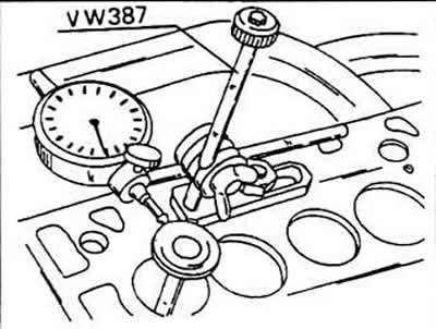
Move the spring plate from side to side; follow the indications of the arrow indicator. If they are more than 1 mm for exhaust, then in most cases the valve guide should be changed.
Check the general condition of the cylinder head before changing the valve guide. Can be reused (grinding) cylinder heads that have small cracks if their width does not exceed 0.5 mm. If the cylinder head is ground, it is necessary to measure its height in the area (A). To do this, place the cylinder head on a smooth surface and measure with a depth gauge through the indicated screw hole. The distance between the top of the head and the measuring plane must be 118.1 mm.
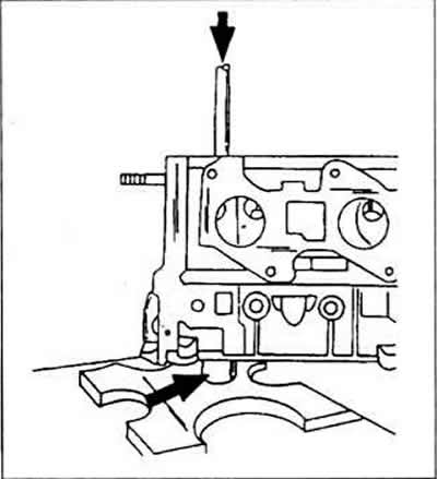
To replace the valve guide, use a suitable drift to press the old guide out of the cylinder head on the combustion chamber side. To facilitate work, the cylinder head can be heated. To the mandrel used for dismantling, you need to screw a pin that fits the size of the inside of the guide. Support the cylinder head with a piece of pipe in the place indicated by the arrow so that the guide can be pressed out.
When replacing guides, the valves are also changed. In this case, you can grind the saddles.
Coat the new guides well with oil and press them from the camshaft side into the cold cylinder head until the guide shoulder is pressed against the cylinder head. After that, the pressing force should not exceed 1 ton, otherwise the collar can be cut off. Since the guides sit at an angle in the cylinder head, the head must be properly supported so that the guide can be pressed in vertically.
After pressing in, process the valve guides with a special reamer 3120. If such a screwdriver is not available, an adjustable reamer can be used. Process the guides of the inlet and exhaust valves with a 7 mm reamer. In this case, the valve guide clearance required according to the instructions will automatically be obtained.
Visitor comments