
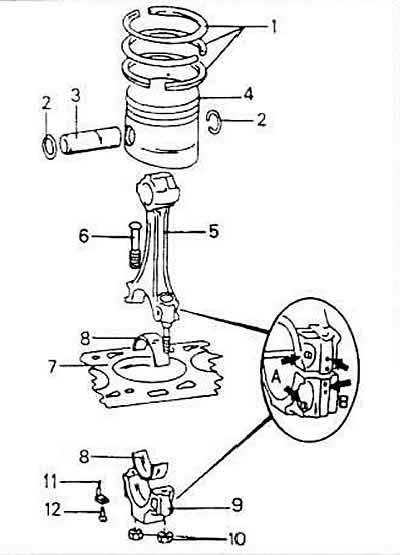
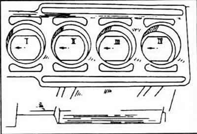
A - marking of connecting rods and caps;
B - position of cast tubercles;
1 - piston rings;
2 - snap ring for the piston pin;
3 - piston pin;
4 - piston;
5 - connecting rod:
6 - connecting rod screw;
7 - cylinder block;
8 - connecting rod bearing shells;
9 - connecting rod bearing cover;
10 connecting rod cap nuts;
12 - screw, 10 Nm.
Dismantling
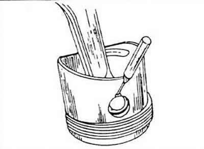
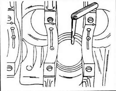
Pistons and connecting rods are pushed up from the inside of the cylinder block using a hammer handle and after removing the connecting rod bearing caps and liners. Before carrying out this work, the following instructions regarding marking, installation direction, etc., must be observed.
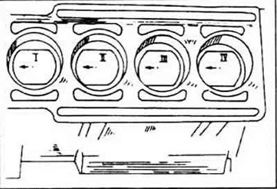
Label each piston and associated connecting rod with the number of the cylinder from which they were removed. This is best done by marking the cylinder number with paint on the piston crown, and also paint an arrow on the piston crown facing the front of the engine.
When dismantling the piston together with the connecting rods, pay attention to the correct direction of installation of the connecting rod bearing cover and immediately after dismantling, mark the connecting rod and the bearing cover on one side with the cylinder number. The best way to do this is with a punch (cylinder No. 1 - one punch punch, etc.).
Connecting rods and covers must be assembled in such a way that both cast tubercles are opposite each other. Both tubercles, after installation, face the crankshaft belt pulley.
Oil sprayers are installed to cool the pistons.
Mark the bearing shells to match the specific connecting rod and bearing cap. Also paint on the back of the upper and lower bearing shells.
When dismantling the pistons, proceed as follows.
Remove the bearing caps and bushings and push out the parts as mentioned above. If necessary, scrape off the oil seal ring on the top side of the cylinder bores with a scraper.
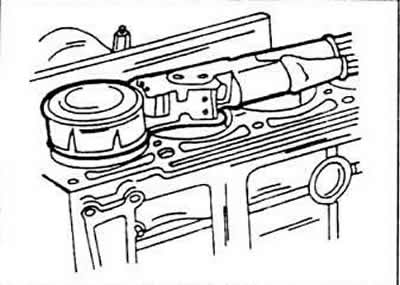
Press out the piston rings after the retaining clips have been removed. Due to the presence of a recess in the inspection hole of the piston, a mandrel can be inserted to remove the locking elements. Using a piston mandrel, press out the piston pin.
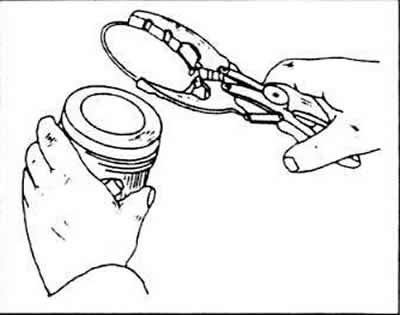
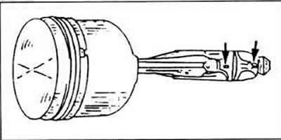
Remove the piston rings one by one using special pliers to remove the rings, moving them towards the piston crown. If the rings are to be reused, they should be marked accordingly.
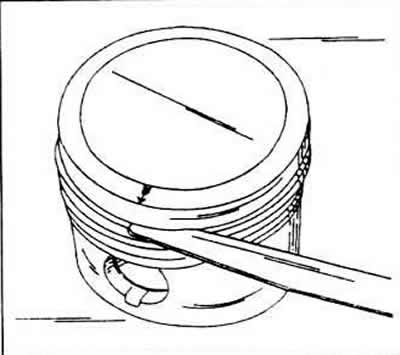
If suitable piston ring pliers are not available, metal strips can be inserted under the ring from opposite sides. To avoid scratches, the strip must be moved down under the ring.
Measuring cylinder bores
To measure the inner diameters of cylinders, you need a cylindrical dial indicator, with which you can measure the top side, middle part and bottom side of the bore. If there is no dial indicator, the following operations can be carried out. - Measure the inner diameters of the cylinders in the longitudinal and transverse directions. Also, measure 10mm from the top edge, 10mm from the bottom edge, and again in the middle. Thus, it is necessary to carry out a total of six measurements of each cylindrical hole. Write down all the data obtained and compare them with those given in the table of sizes and adjustment parameters.
You should pay attention to that. that all cylinders must be additionally bored if the size of at least one of the cylinders does not fit into the table. A deviation of 0.08 mm from the specified dimensions is permissible. Oversized pistons, the dimensions of which are indicated in the table of dimensions and adjustment parameters, are commercially available. The final size of the cylinder bore is determined by measuring the piston 10 mm from the lower edge of the piston trunk and at right angles to the piston pin bore; then to this value it is necessary to add the working clearance of the piston, equal to 0.03 mm. In addition, the final honing must be taken into account by adding 0.02 mm.
To control the working clearance of the piston, it is necessary to measure the piston and the inner diameter of the cylinder in the described way and calculate the difference between the dimensions for the cylinder diameter. If the result is more than 0.08 mm, the cylinders must be ground.
Checking pistons and connecting rods
Check all details carefully. In case of signs of scuffing, scratches or wear of parts, they must be replaced. Carry out the following piston tests.
Measure the piston ring gap height in the piston grooves by inserting the piston rings one by one into the corresponding groove. Using a thickness gauge, determine the size of the gap between the planes of the ring and the piston groove. If any ring gap exceeds 0.15 mm, either it or the piston is worn. The nominal value of the gap lies in the range of 0.02-0.05 mm.
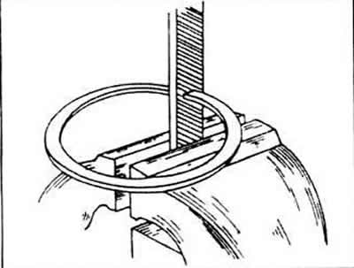
Alternately, from the underside of the crankcase, insert all piston rings to the cylinder bores. Turning the piston over, press on the rings, shifting them down by 15 mm. Thanks to this, they will sit in the hole without distortion.
Insert a feeler gauge into the gap between both ends of the rings to measure the butt gap of the piston rings. For sealing rings, the gap is 0.3-0.45 mm; for oil scraper rings - 0.25-0.64 mm. The wear limit of all rings is 1 mm.
With too little clearance (for example, for new rings, which also need to be measured), the ends of the rings can be filed. To do this, clamp a personal file in a vise; if the joint gap is too large, the corresponding ring must be replaced.
Check the piston pin and connecting rod bushing for wear and scoring. Even if only one connecting rod has lost its functional qualities, the entire set must be replaced.
Connecting rod bearing nuts should always be replaced.
Using a connecting rod driver, check the connecting rods for twisting or bending.
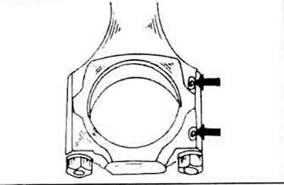
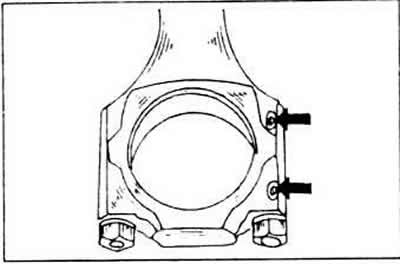
Check the connecting rod bearing screws for damage and replace if necessary.
Connecting rod piston assembly
If the nozzles intended for piston cooling have been dismantled, lubricate the screws with thread protector AMV 188 100.02; Reinstall the nozzles and tighten the screws to a torque of 10 Nm.
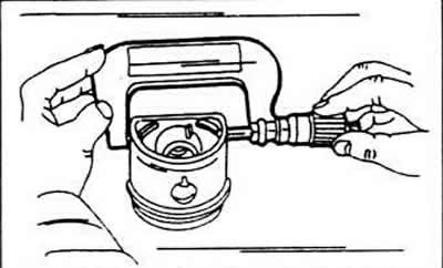
Heat up the piston to 60°C (put in hot water). Use a suitable mandrel that can be inserted into the inside of the piston pin.
Press the piston pin into the heated piston and connecting rod by hand.
When assembling pistons and connecting rods, the following must be taken into account.
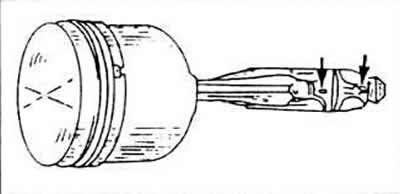
Arrow on the bottom of the piston (painted or embossed in new pistons) must face the front of the engine.
The molded knobs on the connecting rod and bearing cap must face the engine belt pulley.
The cylinder number designations on the connecting rod and bearing cap must match.
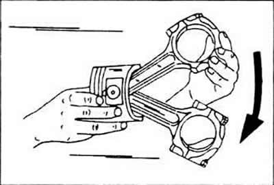
Check that, after assembly, the piston has a perfect reciprocating action on the connecting rod - arrow.
Using piston ring pliers, insert the piston rings one by one into the grooves. It is possible to mix up both O-rings, so look at the cross sections before installing them. In addition, both O-rings are marked on one side with the words «Thor» («Bottom») or «Oben» («Up»); after putting on the ring, this inscription must be visible respectively from the side of the piston crown.
Installation of pistons and connecting rods
Lubricate the cylinder bores well with oil.
All connecting rods are designed for the corresponding cylinder numbers. The molded knobs on the connecting rod and bearing cap should point towards the crankshaft belt pulley.
The arrows on the piston crown must face the front of the engine.
Spread the piston ring joints evenly around the piston at an angle of 120°from each other.
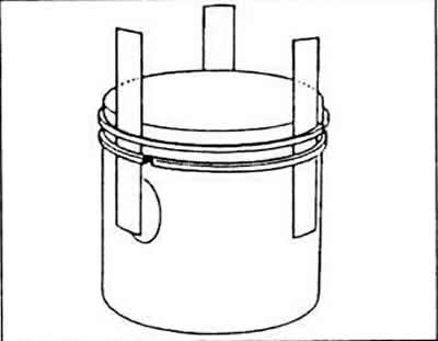
Wrap the piston rings with a belt to secure the piston rings and press the rings into the grooves. Check that they are optimally pressed into the grooves.
To avoid scratching the hole, put short rubber or plastic sleeves over the connecting rod studs.
Rotate the crankshaft until the two connecting rod journals are at dead center.
Insert the connecting rod from above into the hole. To do this, lay the engine on its side so that you can guide the connecting rod onto the bearing journal without scratching the hole or connecting rod pin. The connecting rod bearing shell should already be on the connecting rod, with the lip in the recess.
Move the piston until the rings alternately slide into the hole and the connecting rod leg sits on the crankpin.
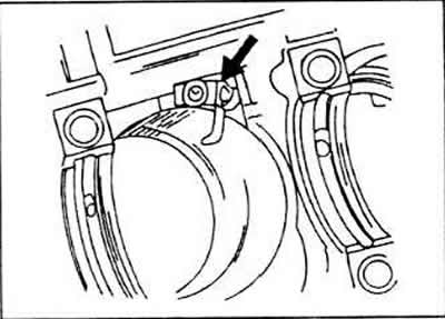
Insert the second bearing shell into the bearing cap, lubricate the shell well with oil, press the cap against the connecting rod studs and tap lightly. Of course, you first need to remove the rubber sleeves again. Be sure to make sure that both molded installation marks converge, since at the last moment it is still possible to make a mistake.
Lubricate the contact surfaces of the nuts on the connecting rod bearing cap with oil.
Alternately tighten the connecting rod bearing cap nuts to a tightening torque of 30 Nm and from this end position turn them a further 90°, i.e. a quarter turn.
After installing the connecting rod, turn the crankshaft several times. to immediately identify pinch points.
Check the markings on all connecting rods again and also see if the pistons are turned in the right direction.
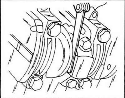
Using a thickness gauge, measure the clearance between the side of the connecting rod and the thrust surface of the crankshaft. This is the axial clearance of the connecting rod bearings, its value should not exceed 0.37 mm.
Mount the oil bath.
Visitor comments