
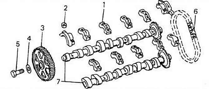
1 - bearing cover
2 - nut, 15 Nm
3 - camshaft flywheel
4 - washer
5 - screw, 65 Nm
6 - drive chain
7 camshafts
The intake control valve is marked with a number in the area between the pair of cams of the third and fourth cylinders. Install only a shaft with the same designation. Your distributor will be able to sell you a suitable shaft if you provide the model, year and engine number of the vehicle.
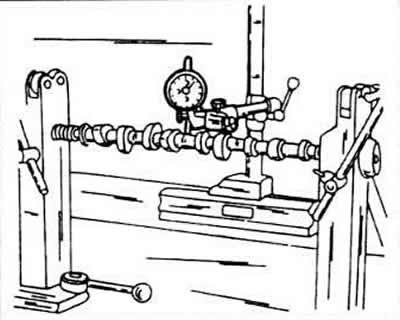
Insert both end bearing journals of the camshafts into prisms or clamp them between the thrust centers of the lathe, and place a dial gauge in the area of the central bearing journal. Slowly rotate the camshaft and read the dial indicator. If the indicator reading is more than 0.01 mm. the shaft is bent and must be replaced, check for visible damage to the bearing pins.
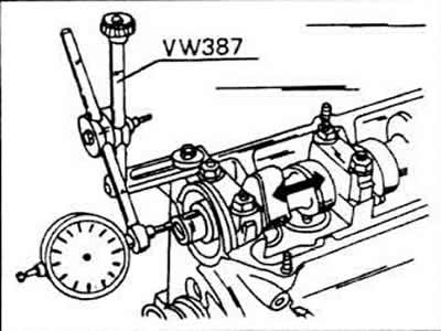
To measure the axial clearance of the camshafts, insert them into the cylinder head (without pushers) and secure with front and rear bearing caps. Place the cylinder head on a smooth surface.
Place the dial indicator at the end surface and move the shaft from side to side, the gap should not exceed 0.15 mm. Otherwise, the pressing surface of the bearing cover is worn.
Visitor comments