
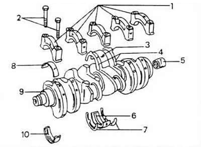
1 - main bearing caps
2 - cover screws, 65 Nm
3 - main bearing shell No. 3
4 - thrust washer for the main bearing cap
5 - needle roller bearing
7 - thrust washer for cylinder block
8 - shells of main bearings in bearing caps
9 - crankshaft
10 - liners of main bearings in bearing caps
Removing the crankshaft
To dismantle the crankshaft, the engine must be dismantled.
Unclip the engine gearbox. When removing the gearbox, do not bend the clutch shaft.
While holding the clutch ring gear with a screwdriver, remove the clutch screws. Most often, the screws can also be removed with a ring spanner, then it is not necessary to hold the clutch. To do this, put the ring key at a right angle and tap the end of the key with your hand. In most cases, the screws come loose by tapping.
Before dismantling the clutch, strike the pressure plate and flywheel with a punch to mark both parts together, from the front of the engine, remove the crankshaft belt pulley screw until the flywheel can be held.
Disconnect the cylinder head together with the suction channel.
Unscrew the belt pulley from the water pump and the bottom cover protecting the toothed belt.
Mark the direction of movement of the toothed belt with paint on the outside.
After loosening the clamp nut, remove the toothed belt from the flywheels and the belt tensioner. Now do not turn the camshaft.
Unscrew the oil bath.
Remove the oil pump.
If only the crankshaft needs to be removed, the pistons and connecting rods may remain in the cylinder block. Otherwise, dismantle. Otherwise, dismantle the pistons and connecting rods. If the pistons remain in the block, mark and remove the connecting rod bearing caps one at a time and keep them together with the liners. Remember that used flexible screws should be replaced if they are damaged.
Place the dial indicator with the stand on the front side of the cylinder block so that the measuring foot is put on the end pin of the crankshaft. Use a screwdriver to press the crankshaft to the side, set the indicator to zero and press the shaft in the other direction. The indicator shows the axial clearance of the crankshaft. This reading should be recorded for subsequent assembly, if it exceeds 0.25 mm, this must be taken into account during installation. The middle bearing shells are equipped with thrust washers. Thrust half washers perceive the axial pressure of the crankshaft.
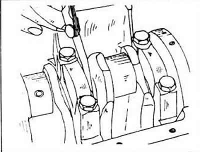
In the absence of a dial indicator, you can also measure the clearance on the middle bearing between the bearing flange and the surface of the crankshaft using a thickness gauge.
Loosen the fixing screws of the sealing flange on the front of the motor and remove the flange together with the seal.
Remove the motor intermediate plate, remove the O-ring flange screws and remove the flange together with the O-ring. Fitted bushings serve as guides for the intermediate plate of the engine.
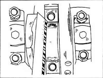
Evenly, crosswise, disconnect the screws of the crankshaft bearing caps and remove them one by one. check that the numbers on the cover are clearly visible. Cover No. 1 is located on the side of the belt pulley.
Remove the bearing shells from the bearing journals and fold them together with the corresponding bearing caps.
Remove the remaining liners from the crankcase and fold them together with other liners and covers. These bearing shells are provided with lubrication grooves and must be re-inserted into the crankcase during assembly. Remove the bottom thrust washers. placed on the middle bearing. If the same thrust washers are installed again, store them securely. not to damage work surfaces. Otherwise, discard the washers.
Checking the parts of the crankshaft
Carefully check for damage to the crankshaft: accurately measure the journals of the main and connecting rod bearings. The crankshaft main bearing journals and connecting rod pins can be reground up to three times. therefore the shaft can be mounted together with oversized bearing shells.
Clamp the crankshaft between the thrust centers of the lathe (or insert both outer bearing pins into the prisms) and using a dial indicator mounted on the middle support pin, check for runout. The runout should not exceed 0.06 mm. Otherwise, replace the shaft.
Measure the operating clearance in the main and connecting rod bearings.
Clean the bearing shells well and insert them into the bearing holes in the cylinder block or into the connecting rods.
Wrap all main bearing journals with plastic strip «Plastigage» and fit all main bearing caps with bearing shells inserted. Tighten the screws to a tightening torque of 65 Nm. Do not turn the shaft any more.
To control the clearance of the connecting rod, install the connecting rod against the crankpin and lay on the top side of the crankpin «Plastigage». fit the bearing cover together with the shell and tighten the nuts to a tightening torque of 30 Nm. Since the shaft can no longer be turned, the two connecting rod bearings are checked respectively. located at bottom dead center.
For main bearings, unscrew the cap, for connecting rod bearings, unscrew both caps in turn.
Using the caliber supplied «Plastigage», measure the widest part of the flattened strip «Plastigage». If the dimension is greater than 0.17 mm for main bearings or 0.12 mm for connecting rod bearings, new bearing shells must be used; In this case, it must be taken into account whether the support pins have already been ground.
If the test passes the operating clearance of the connecting rod bearings, turn the crankshaft and inspect the other two connecting rod bearing journals by measuring them as described above.
Mounting the crankshaft
Wipe blind holes clean and insert bearing shells equipped with lubrication grooves so that the guide tabs of the shells fit into the recesses of the blind holes. Lubricate the bearings well.
Place both thrust washers used in the block on the middle bearing if the bearing shells have not been replaced.
Carefully insert the crankshaft into the bearing shells. If the connecting rods are still in the cylinder block, the connecting rod bearings must be installed on the connecting rod journals.
Insert the lower crankshaft bearing shells (protrusions into grooves) and well lubricate the surfaces, if they are mounted, put the other two thrust washers on the cover. The oil grooves fit on the crankshaft.
Place the covers on the crankcase and tap with a rubber or plastic mallet.
Tighten the cover screws in several steps (moving from the center to the outside) up to a moment equal to 65 Nm. After tightening the caps, rotate the crankshaft several times. to determine now the pinch points.
Check the end play again.
Mount pistons and connecting rods.
Install both oil seals.
Using the key, mount the crankshaft flywheel.
Install the control belt.
On vehicles with a gearbox, fit the flywheel. Screws should always be replaced. Lubricate the screw threads with thread protectant D6. The tightening torque is 100 Nm. Lock the crankshaft. inserting a wooden block between the cheek of the crankshaft and the crankcase wall.
Install flywheel and clutch.
Mount the oil pump.
Apply a new oil bath seal with grease and install the oil bath. Tighten the hexagon head screws to a torque of 20 Nm.
Visitor comments