



Note: The adjustment must be made in the order specified, since the torques of the bearings are adjusted taking into account the torques of all rotating parts of the gearbox. Before disassembling, if the bearings are to be used again, measure and record the torques of the bearings that must be maintained during assembly. The bearings must be lubricated with gearbox oil.
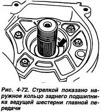
When adjusting, the outer race of the rear bearing (Fig. 4-72) must be installed and calked. The selector lever lock cable and parking brake toothed locking wheel must be installed.
Install two mounting rings, each 1.5 mm thick, on the drive shaft-pinion. Install the driven gear of the main gear drive on the end of the drive shaft-pinion of the main gear and tighten the hexagonal nut "at 41" with a torque of 25 kgf·m, applying the parking brake.
Attach the indicator stand to the gearbox housing (Fig. 4-73). Place the mandrel on the end of the drive shaft-gear. Mount the indicator on the stand so that its leg rests on the mandrel with a preliminary tension of 1 mm. Fix the indicator in this position and set its pointer to zero. By moving the drive shaft-gear up and down, determine its axial displacement by the indicator, which is, for example, 0.93 mm.
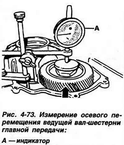
Warning: When measuring the axial displacement of the main gear drive shaft, do not allow it to rotate, since the self-alignment of the bearing rollers that occurs during rotation disrupts the accuracy of the measurement.
(The original can be viewed on the portal: VWmanual.ru)
Using the formula S=A-(B+C+D), calculate the thickness of the adjusting ring of the bearings of the main gear drive shaft, where:
S — thickness of the adjusting ring;
A - total thickness of the mounting rings;
B is the value of axial displacement of the main transmission drive shaft-pinion;
C — the value of the preliminary tension of the bearings of the main transmission drive shaft-pinion;
D — the value of self-alignment of the bearing rollers of the main transmission drive shaft gear.
Example.The thickness of the mounting rings is 3.00 mm, the measured axial displacement of the driving pinion shaft is 0.93 mm. The value of the preliminary load of the bearings of the driving pinion shaft is 0.12 mm. The value of self-alignment of the bearing rollers is 0.10 mm. S = 3.00 - (0.93 + 0.12 + 0.10) = 1.85 mm.
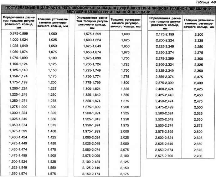
Determine the thickness of the adjusting ring according to Table 4-9.
Remove the driven gear of the main transmission drive and the adjusting rings. Install the selected adjusting ring on the driving shaft-gear of the main transmission.
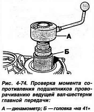
Install the driven gear of the main transmission drive, screw a nut onto the end of the main transmission drive pinion shaft and tighten to a torque of 25 kgf·m. Then lock the nut by pressing the holes on the nut neck. Put a "41" head on the nut (Fig. 4-74) and use a dynamometer to measure the moment of resistance of the bearings to turning of the main transmission drive pinion shaft, which for new bearings (before installation, lubricate the bearings with gearbox oil) should be within 0.8-1.2 Nm.
Visitor comments