



Gearbox drive
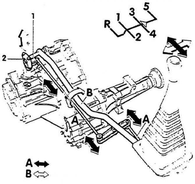
1. Gear shift lever; 2. Fork head for gear selection; A. Shift rods; Arrow A. Switching movement; Arrow B. Movement of choice
Switch housing
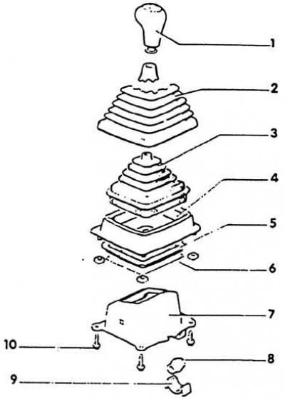
1. Shift knob – press into the corrugated boot (2); 2. Corrugated cover – inserted into the frame (4); 3. Cuff – not available in all machines. Installed together with the frame (4). The inscription "vorn" (forward) indicates the direction of movement.; 4. Frame – place on the shift housing (7) and the mounting screw. The inscription "vorn" (forward) indicates the direction of movement; 5. Gasket – installed between the frame and the bottom. The arrow-like marking points in the direction of travel; 6. Bottom; 7. Switch housing; 8. Support sleeve with shift bracket; 9. Bushing insert - when removing, squeeze both jumpers; 10. Screw, 9 Nm
Shift lever
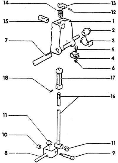
1. Shift bracket – remove together with the shift lever (16), after first removing parts (8, 7, 3) from the shift lever or shift bracket; 2. Support sleeve; 3. Bushing insert; 4. Tubular clamp - loosen to adjust the shift drive and remove the shift bracket and selector rod; 5. Fastening screw; 6. Nut, 18 Nm; 7. The pull of choice; 8. Rear shift rod 9. Guide screw; 10. Nut, 5 Nm – self-locking, so always replace; 11. Support sleeve; 12. Threaded pin; 13. Emphasis; 14. Pressure spring; 15. Support finger; 16. Gear Lever – Cars with individual seats: the gear lever at the rear is slanted backwards. Cars with a common seat: the gear lever at the rear is not slanted.; 17. Guide bushing; 18. Locking pin - knock out with a tenon
Shift rods and selector rods
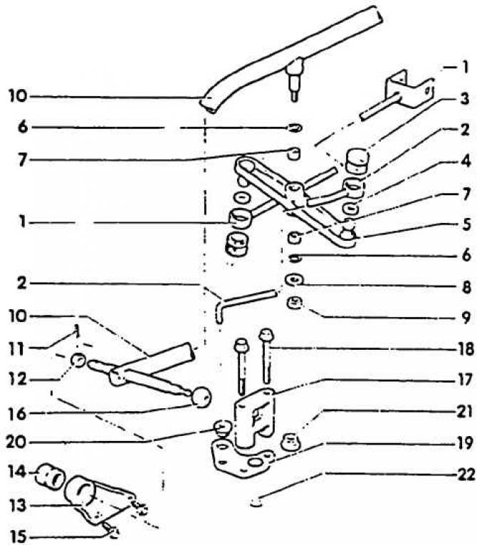
1. Rear shift rod; 2. Front shift rod; 3. Bushing; 4 Sealing washer; 5. Bypass lever; 6. Round ring; 7. Support sleeve; 8. Washer; 9. Fastening nut, 25 Nm; 10. The pull of choice (remove from gearbox together with bearing bracket 13); 11. Locking sleeve; 12. Ball joint; 13. Bearing bracket; 14. Bushing; 15. Bearing bracket-gearbox mounting screws, 20 Nm; 16. Ball joint of the selection rod in the fork head; 17. Fork head; 18. Screw, 9 Nm; 19. Gear shift lever. Installed in one position only; 20. Front shift rod support bushing; 21. Nut, 25 Nm; 22. Gearbox shift shaft
The original article is available on the website www.vwmanual.ru
Adjustment
1. Set the gearbox to neutral and apply the handbrake.
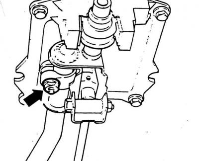
2. Loosen the clamping clamp (arrow). The connection between the selector rod and the shift bracket should be free to move.
3. Remove the shift knob and the bellows.
4. Remove the frame with the cuff.
Attention! The contact surfaces of the stop and the switch housing must be parallel to each other. If necessary, align the stop with the VW-3258 template before installation.

5. Install the template until it stops and tighten it with the screw (arrow).
6. Adjust the selection rod-shift bracket without tension (box in neutral position) and tighten the clamp to a torque of 20 Nm.
7. Pull the shift lever toward the rear seat, loosen the screw and remove the template.
Checking the gap
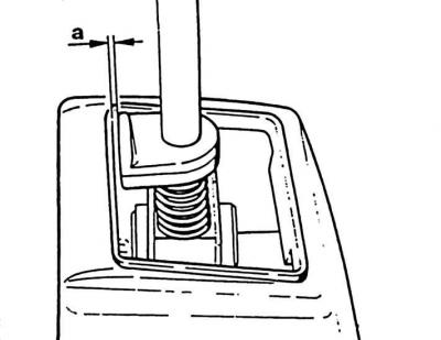
a. Gap
Checking the work
1. The gear shift lever should be in neutral position opposite 3–4 gear.
2. The bottom of the shift lever, below the bend, should be vertical.
3. Press the clutch, start the engine, wait about 3-6 seconds for the gearbox drive shaft to stop, then repeatedly engage all gears. Pay attention to the operation of the reverse gear lock.
4. Install the frame with the cuff and the shift handle with the corrugated boot.
5. If the gear shift still sticks when you re-engage any gear, engage 1st gear.
6. Remove the gap in the shift drive by pressing the shift lever to the left with 1st gear engaged and applying a force of 2–3 N on the shift handle thread. Gap (distance shift lever stop-shift housing stop) in this position should be: a = 1.3–2.3 mm.
7. Otherwise, turn off 1st gear and repeat the drive adjustment.
8. Signs of correct shift adjustment are: flawless operation and interaction of the shift drive components and ease of movement of the shift drive.
Visitor comments