
Removing
1. Disconnect ground cable (-) from the battery.
Attention! At the same time, the anti-theft code is erased from the radio's memory. Disconnect the battery only when the ignition is off. Otherwise, the injection system control unit will be damaged.
2. Remove the clutch cable from the retaining bracket.
3. Fold out the radiator (see subsection 2.2).
4. Mark with adhesive tape and disconnect all cable connections from the gearbox and starter.
5. If equipped, disconnect wiring harness from coolant hoses. Mark the location with a felt-tip pen in order to install it in the old place during assembly.
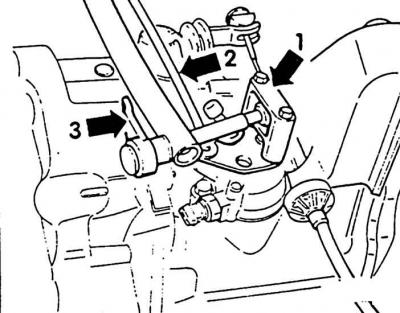
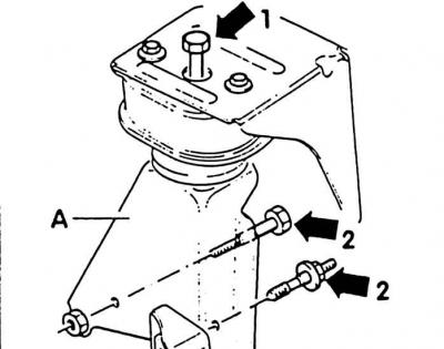
6. Disconnect the shift actuator from the gearbox. To do this, unscrew the fork head (1). Remove shift rod from front (2) from the gear lever. Unscrew bearing bracket with gear selector rod (3). Tie up the shift rod and the gear selector rod.
7. Remove clutch drive. To do this, on machines with a hydraulic clutch, unscrew the slave cylinder from the gearbox, set aside and secure with wire.
Attention! Do not open the hydraulic system. Otherwise, after assembly, it will be necessary to bleed air from the system. Do not depress the clutch pedal with the slave cylinder removed.
8. On machines with a mechanical clutch, disconnect the clutch cable from the gearbox and gearbox bearing bracket (see subsection 3.2).
9. Remove the speedometer drive shaft bracket from the transmission.
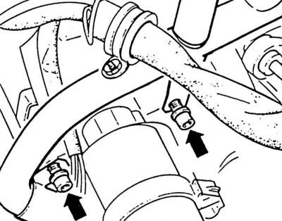
10. Unscrew the coolant line from the starter from the expansion tank to the water pump (arrows show mounting bolts).
11. Unscrew the electrical wiring from the pipeline.
12. Unscrew the upper screws securing the engine-gearbox.
13. Petrol engine: Disconnect the brake booster vacuum hose from the engine.
14. 4-cylinder diesel engine: Disconnect the cable drives from the engine.
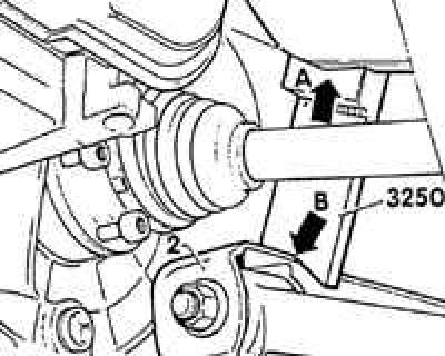
15. Mount the support device VW-3250 on both sides so that the left axle shaft, shock absorber screw and connecting rod (right stabilizer) could be removed. Emphasis (A) support must be in front of the upper steering knuckle. V-neck (IN) rests against the mounting bracket (2).
Attention! Install the support device VW-3250 before lifting the machine, otherwise the machine will again be under the influence of springs or loads.
16. Remove the left axle.
17. Detach the left axle shaft flange from the gearbox.
18. Unscrew the shock absorber screw and connecting rod from the right (stabilizer).
19. Unscrew ground connections (-) from the gearbox and bearing bracket.
20. Remove starter (see subsection 10.18.1).
21. Diesel engine: Disconnect the brake booster vacuum hose from the vacuum pump on the engine.
22. 5-cylinder engine: remove alternator (see subsection 10.17.2).
23. Disconnect the transmission carrier (A) from the bearing housing (IN) and from the engine. The figure shows the gearbox support of a 4-cylinder engine.
24. 4-cylinder engine: unscrew the screw securing the engine-gearbox above the bearing housing.
25. 4-cylinder engine: remove flywheel guard from below.
26. Air conditioner: remove the compressor, set aside and hang on a wire.
Attention! Do not open pipelines.
27. Up to 8/92 (date of manufacture of the box 08/09/92): Remove the rear transmission support together with the console. Move the engine-gearbox assembly slightly forward if necessary.
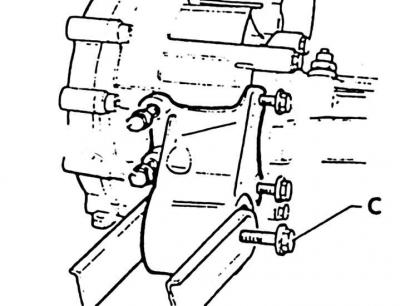
28. From 8/92 (date of manufacture of the box 08/10/92): Unscrew the rear engine-gearbox support. Loosen the bolt (WITH), tilt the transmission forward and remove the transmission support.
29. Remove the speedometer drive shaft from the right hand flange shaft bearing housing.
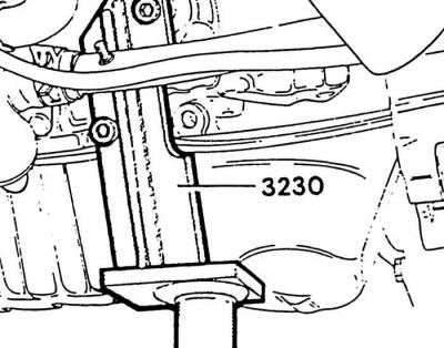
30. Screw the VW-3230 engine mount as shown above.
Attention! 5-cylinder engine requires VW-3227 engine support.
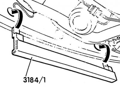
31. Hang auxiliary rail VW-3184/1, to accommodate VW-3184, on the front end beam. If necessary, disconnect interfering piping and wiring.
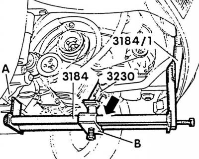
32. Suspend the VW-3184 detachable device from the front on the auxiliary rail VW-3184/1 and from the rear on the brackets of mounted units (A), while inserting the pin of the VW-3230 support device into the hole of the movable slide (IN).
Attention! With the correct installation of the sled pickup (IN) adjacent to the right pipe (arrow).
33. After installation, tighten the stoppers of the removable tool.
34. Clamp the spindle (WITH) removable fixture.
35. bearing bracket (A) first unscrew the gearbox from the rubber-metal support on the body (1), then gearboxes (2).
Attention! To remove the bearing bracket from the gearbox, lower the unit.
36. Press the stabilizer of both connecting rods up to the stop to make room for the exhaust pipe.
Attention! Cover the anti-roll bar and, if there is a steering damper, in the area of the exhaust system so that the protective paint layer is not damaged.
37. Disconnect the front exhaust pipe from the additional muffler or catalytic converter (see subsection 2.19.1).
38. 4-cylinder engine: unscrew the safety guard pipe-auxiliary tank.
39. Rock the engine and gearbox assembly forward and lower alternately while holding the right axle shaft so that it rests on the gearbox pivot flange.
40. 5-cylinder engine: Unscrew the engine-gearbox mounting screws on the right above the drive shaft bearing housing.
41. Install a VW-1383 jack under the gearbox and unscrew the remaining screws securing the engine-gearbox.
42. Secure the gearbox, press it away from the engine and lower it carefully.
Installation
1. Check clutch before installing (see subsection 3.2).
2. Check release bearing free play.
Attention! Only wipe the bearing, do not rinse. If before removal, when depressing the clutch pedal, noises were heard in the bearing, replace the bearing.
3. Clean drive shaft splines and lubricate with a thin coat of Moly Glide Paste or Moly Spray.
Attention! If the gearbox is replaced, the shift lever is always adjusted as well.
4. Before installing the gearbox, press the clutch release lever against the gearbox housing and secure it with a collar pin or M8x22 screw.
5. On machines with power steering, before installing the gearbox, install the screws securing the bearing housing to the gearbox in the holes of the bearing housing.
6. Raise gearbox and slide horizontally into clutch. If during installation the drive shaft of the gearbox does not fit into the clutch disc, turn the drive shaft, from behind, behind the propeller shaft flange, by hand. When installing the gearbox, pay attention to the correct position of the protective guard.
7. Screw in the screws securing the engine-gearbox as far as possible.
Visitor comments