
Removing
Disconnect ground wire (-) battery.
Attention: this erases the engine fault codes and the radio code from the memory device. The battery can only be disconnected when the ignition is off, otherwise the injection control unit will fail. Before disconnecting, you must also read the instructions in the section «Removal and installation of radio», and «Removing and installing the battery».
Disconnect the electrical connectors at the gearbox.
Turbocharged diesel engine: Remove the air hose from the turbocharger to the charge air cooler.
Remove the shift lever and guide lever, as well as the cable tie rod support at the gearbox, see below.
Vehicles with hydraulic clutch:
Dismantle the shift cable with guide lever so that the slave cylinder can be removed, see below.
Unscrew the clutch slave cylinder and hang it on a wire to the body.
Caution: The hydraulic actuator remains connected, otherwise the system must be vented after installation. With the slave cylinder removed, do not depress the clutch pedal.
Vehicles with a mechanical clutch: Disconnect the clutch cable from the shift lever at the gearbox and from the support, see chapter «Clutch». Vehicles with a mechanical speed indicator: Unscrew the speed indicator drive shaft from the gearbox.
Vehicles with electronic speed indicator: Disconnect plug from speed sensor.
Remove the 4 upper engine and gearbox mounting bolts.
Raise the car, see section «Vehicle lifting».
Disconnect the front exhaust pipe from the exhaust pipe and support it on a wooden stand.
Remove starter, see chapter «Electrical system».
Unscrew the protective screen of the cardan shaft.
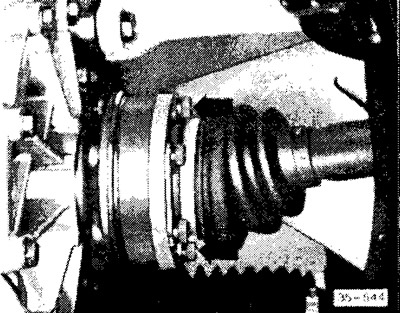
Unscrew cardan shafts on the left and right of the gearbox and tie both shafts high.
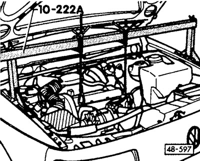
Install a suspension device, for example, VW 10-222A, and pre-tighten the engine with a lead screw. If there is no suspension device, place a suitable rod on the trestle and tighten the engine with a cable.
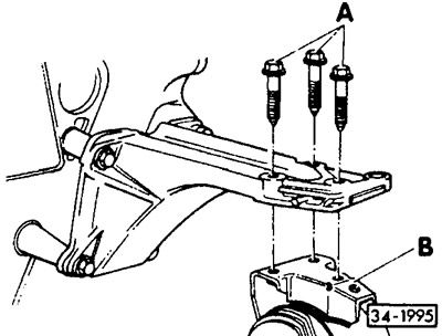
Remove 3 bolts -A- at right engine support -B-.
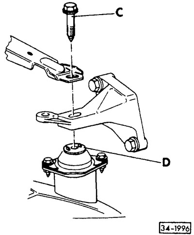
Remove bolt -C- at left gearbox support -D-.
Attention: The bolt is somewhat difficult to access. On vehicles with power steering, carefully press hydraulic lines to one side. On vehicles with anti-blocking device, if necessary, remove coolant expansion tank, see chapter «Cooling system».
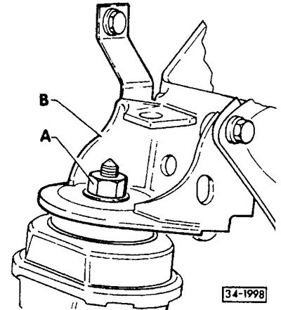
Loosen nut -A- at front engine mount.
Remove front console -B- for engine mounts.
If available, tie the power steering hoses together and tie them securely to the front of the body, eg to the front engine mount.
Unbolt shock absorber from front axle beam, see chapter «Front axle».
Move the power unit to the right as far as possible and raise the engine a little more with a cable.
Attention: If there is not enough space, remove the radiator fan, see chapter «Cooling system».
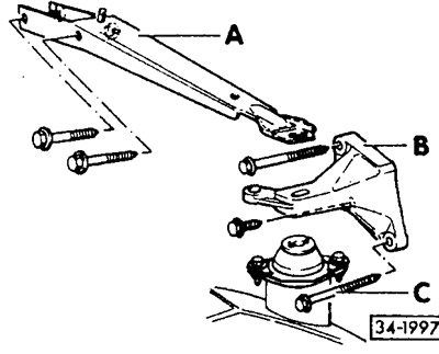
Unbolt support -A- and console -B- from gearbox. Press the power unit against the front wall of the body and pull out the mounting bolt -C- from the gearbox console.
Attention: As of 4/93, the gearbox console is no longer fitted. If there is a console, then during assembly it must be installed again.
Loosen and remove the small transmission shield.
It is easy to raise the gearbox with a V.A.G 1383 jack. If there is none, raise the gearbox with a garage jack.
Caution: Place a piece of wood between the gearbox and the jack.
Loosen the engine/gearbox mounting bolts.
Press gearbox off guide bushings and carefully remove.
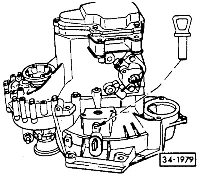
Press the clutch release lever against the gearbox housing and lock it with a mounting pin or M8x35 bolt (length 35 mm). After installing the gearbox, pull out the bolt and close the hole with a plug.
Installation
Before installation, check the adhesion, see chapter «Clutch».
Check the clutch release bearing for ease of movement.
Attention: Only wipe the bearing, do not wash it. If there was noise in the bearing when disengaging the clutch before removal, replace the bearing, see chapter «Clutch».
Clean the driveshaft splines and lightly lubricate with anti-friction paste or spray with molybdenum-based anti-friction spray.
Check if there are guide bushings in the engine block for centering the gearbox, otherwise install the bushings.
Raise the gearbox and move it into the clutch in a horizontal position. If, during installation, the drive shaft of the gearbox does not fit into the splines of the clutch disc, then turn the drive shaft by the flange for the propeller shaft by hand until the splines match.
Assembly is carried out in the reverse order to that which took place during removal. Bolts of fastening of the engine/transmission (M12) tighten alternately to 80 Nm.
Install shock absorber and tighten bolts to 30 Nm, see chapter «Front axle».
Install starter, see chapter «Electrical system».
Tighten the gearbox support bolts on the rear left, do not overtighten.
Remove the engine suspension and screw on the front engine support by hand. 0 Fit clutch slave cylinder and tighten bolt to 25 Nm. On vehicles with a mechanical clutch, install a cable tie, see chapter «Clutch».
Install cardan shafts, see chapter «Front axle».
Screw on the propshaft shield.
Tighten clutch cover to 10 Nm.
Install the exhaust system, see chapter «Exhaust system».
Connect the electrical wires to the gearbox.
Turbocharged diesel engine: Install the air hose from the turbocharger to the charge air cooler. To do this, put the hose on the connecting pipes and secure with clamps tightening the screw, 0 Screw the gear change actuator to the gearbox.
Attention: If the cable pulls on the levers have been released, adjust the gear change actuator, see below.
Vehicles with a mechanical speed indicator: Screw the drive shaft of the speed indicator to the gearbox.
Vehicles with electronic speed indicator: Connect the plug to the speed sensor.
Check the oil level in the gearbox, see below.
Align the power unit, tighten the supports to the prescribed torque, see chapter «Engine».
Connect ground wire (-) battery.
Attention: The battery can only be connected when the ignition is off, otherwise the injection system control unit will fail.
Adjust clock.
Enter the radio anti-theft code, see section «Entering the radio code».
Carry out an inspection trip.
Visitor comments