
4 cylinder engine
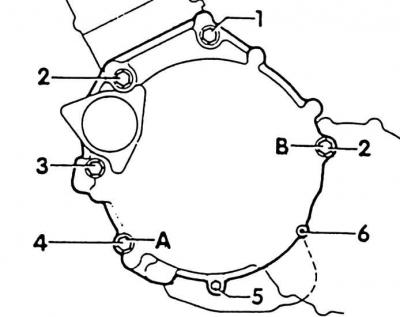
1. Screw M12x130, 80 Nm; 2. 2 screws M12x60, 80 Nm; 3. Screw M12x100, 80 Nm; 5. Screw M8x32, 25 Nm; 6. Screw M8x12, 25 Nm
Guide sleeves for centering in positions A and B.
5 cylinder engine
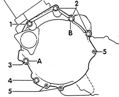
1. Screw M12x60, 80 Nm; 2. 3 screws M12x70, 80 Nm; 3. Screw M12x100, 80 Nm; 4. Screw M12x130, 80 Nm; 5. 3 screws M8x45, 25 Nm
Guide sleeves for centering in positions A and B.
1. Raise the engine and gearbox assembly by swinging alternately. When doing this, position the right axle shaft so that it rests on the gearbox flange shaft.
Attention! To install the bolt of fastening of the support of the units on the left side of the body, the support pin of the engine support and the spindle of the pull-out tool are required (arrow) install exactly in one line. Remove the VW-3184 removal tool only when the screws securing the left support of the units are tightened.
2. 4-cylinder engine: screw on the exhaust pipe-fuel tank guard.
3. Connect the front exhaust pipe to an additional muffler or catalytic converter (see subsection 2.19.1).
4. Press the stabilizer of both connecting rods up to the stop to make room for the exhaust pipe.
5. Tighten bearing bracket on gearbox and rubber mount to 65 Nm.
6. If removed, install electrical wires and pipelines.
7. Remove the VW-3184 removal tool.
8. Unscrew the engine support VW 3230/3227.
9. Install the speedometer drive shaft onto the right engine axle bearing housing.
10. Up to 8/92 (box release date 08/09/92):
- install the rear support engine-gearbox without voltage;
- screws (A) tighten torque 65 Nm (only if the gearbox support was removed);
- screws (IN) tighten to 45 Nm.
Attention! After replacing the gearbox or repairing it, the thickness of the wear plate between the console and the gearbox housing must be measured again. To do this, measure the distance between the console and the gearbox and install a 0.5 mm or 1.0 mm thick plate between them. If the clearance is less than 0.5 mm, do not install the plate.
11. From 8/92 (date of manufacture of the gearbox 10.08.92) a modified rear gearbox mount is installed:
- holes (A) increased from 10 mm to 12 mm;
- the old M10 hexagon screws securing the box support to the attachment bracket are replaced with new M16 hexagon screws (WITH) - a new rear box support cannot be installed in old machines.
12. Since 8/92:
- install the rear support engine-gearbox without voltage;
- screws (A) tighten to 100 Nm;
- screws (IN) tighten to 40 Nm;
- screw (WITH) tighten to 270 Nm.
13. Air conditioning: screw on the compressor.
14. 4-cylinder engine: install lower flywheel guard.
15. 4-cylinder engine: screw in the engine-gearbox mounting screws above the bearing housing (tightening torques: M8 screw - 25 Nm, M12 screw - 80 Nm).
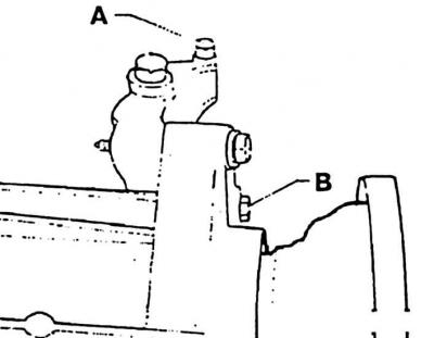
16. Tighten bolts securing carrier gearbox to motor and bearing housing as follows: install bolts (A) And (IN). Tighten the bolts first (A), then bolts (IN).
17. 5-cylinder engine: install a generator.
18. Diesel engine: Connect the brake booster vacuum hose to the vacuum pump.
19. Screw on ground connection (-) gearbox-bearing bracket.
20. Install starter.
21. Screw on the shock absorber screw and the stabilizer connecting rod on the right with a torque of 160 Nm.
22. Attach the right axle shaft of the gearbox.
23. Install the left axle.
24. Remove support tool VW-3250.
25. 4-cylinder diesel engine: install and adjust the cables on the engine (see subsection 2.17.5 and subsection 2.17.6).
26. Petrol engine: Install the brake booster vacuum hose to the engine.
27. Tighten the screws securing the engine-gearbox from above. Tightening torques: M8 screw - 25 Nm; screw M12 - 80 Nm.
28. Attach wiring to piping.
29. Screw the coolant line from the expansion tank to the water pump, to the starter.
30. Install the speedometer drive shaft bracket to the transmission.
31. On machines with a mechanical clutch, attach the clutch cable to the gearbox and gearbox bearing bracket.
32. Mechanical clutch drive: depress the clutch pedal to the stop at least 5 times, then check the operation of the adjusting device (see subsection 3.4).
33. For machines with hydraulic clutch actuation: screw the slave cylinder onto the gearbox with a torque of 25 Nm.
34. Remove the mounting pin or M8x22 screw from the gearbox hole and close the hole with a plug.
35. Install and adjust the shift mechanism on the gearbox.
36. Reinstall the electrical wiring to the coolant hoses in their original locations.
37. Connect, according to the labels with adhesive tape, the cables of the gearbox and starter.
38. Install the radiator (see subsection 2.16.2.1).
39. Connect ground cable (-) to the battery.
Attention! Connect the battery only when the ignition is off. Otherwise, the injection system control unit will fail.
40. Set clock time.
41. Enter the anti-theft code into the radio.
Visitor comments