
Instruction: After unscrewing the bolt, the car must not be lowered to the ground.
Remove the front left wheel. Disconnect the battery. Completely remove the air filter housing. Remove battery and console. Manually release selector lever -1- and remove from counterhold -2-.
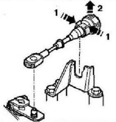
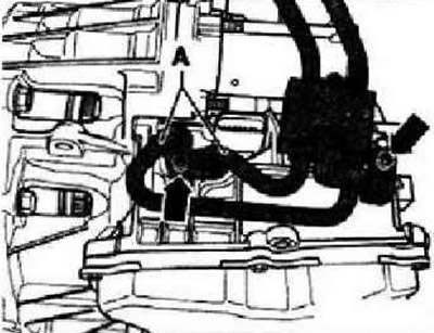
Be careful not to deform the cable. Do not use pliers - clamps on the counterholder may break. Then press the cable from the ball head -2-. Disconnect all electrical connections accessible from above to the gearbox and starter: multifunction switch, starter, ground wire on the console.
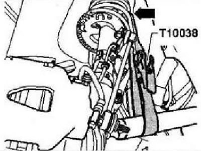
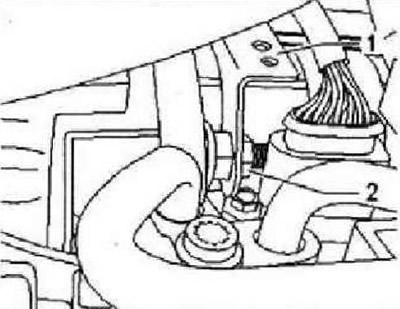
Unscrew top securing nut -1- for cable holder -2-.
Loosen all upper gearbox-to-engine bolts. Raise the car. Remove soundproofing. If necessary: Unplug connector at front left vehicle level sender -G78-.
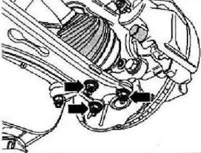
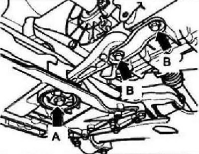
Unscrew -nuts- from both sides of the lower control arm. Press both drive shafts away from the gearbox. Remove left drive shaft.
Raise the right drive shaft as high as possible and secure it in this position on the spring strut.
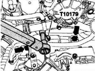
Remove the rocker arm, first -A-, then -B-.
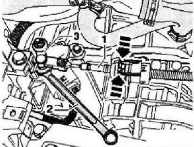
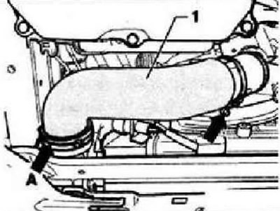
Remove charge hose -1-. Disconnect the two accessible electrical connections of the gearbox from below.
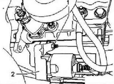
Unscrew the cable holder -1- from the lower starter bolt -Z-. Remove cable holder -1-.
Remove bolts -arrows- and detach ATF lines -A- from gearbox. Seal the gearbox openings and ATF oil lines with clean plugs.
Unscrew the plug.
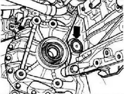
Unscrew the six torque converter nuts through the -hole- using socket -V/175-. While doing this, hold the starter ring gear with a screwdriver.
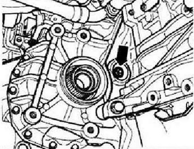
Instructions: Turn the engine with conventional tools at the belt pulley.
Remove all easily accessible connecting bolts between engine and gearbox. Lower the car. Fit cross member -10 - 222 A-. To prevent warping/deformation when unscrewing and tightening the gearbox support, install the hooks -10 - 222 A/10- on the left and right as shown in the figure.
Left (gear side)
Align adapter -10-222 A/18- on traverse -10 - 222 A- so that the hook of the spindle is suspended vertically from the lug on the motor.
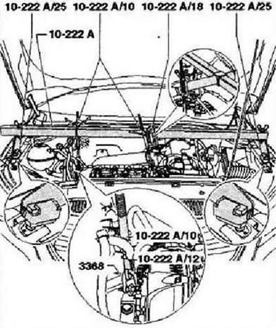
Instructions: In this case, the lead screw is tilted, the upper end is facing the center of the car.
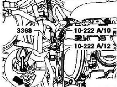
On right (engine side)
Hold M10 nut -arrow- under engine mount. Insert eyebolt -3368- through engine mount. Screw the nut about 8 turns onto the eyebolt. Mount eyelet -10-222 A/12- on eyebolt. Insert the hook -10-222 A/10- into the shackle and align the spindle vertically. To stabilize the traverse, first loosen the spindle, then tighten it 6 turns.
Instructions: After that, turn only the left spindle (gear side).
Support the engine and gearbox. Do not lift.
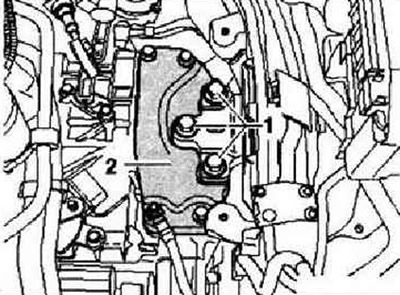
Remove bolts -1- securing gearbox support to bracket. Unbolt bracket -2- from gearbox. Lower the engine/gearbox by approx. 6 turns with the left spindle. Take out the console.
Connect gearbox assembly tool -3282- to setting template 3282/56-. Place tilter -VAG 1383 A- under the gearbox and support it. Do not lift. In this position, the gearbox is disconnected from the engine. Remove the last engine/gearbox connecting bolt. Carefully lower the gearbox, paying attention to the distance to surrounding parts. When lowering the gearbox, pay close attention to the ATF line.
Installation
Installation is carried out in the reverse order. Check that the mounting sleeves are pressed into the motor flange. Make sure the torque converter is installed correctly. It should be easy to rotate by hand and sit evenly deep all around in the gearbox.
Instructions: Carefully unscrew the motor! When installing the gearbox in the engine, attach great importance to the careful rotation of the engine shaft. The starter ring gear can be held from the outside with a screwdriver. Thus, during installation, the studs will go into the holes of the metal gasket of the leash.
The engine and gearbox must be freely suspended in the attachment bracket. Before tightening the bolts, correct the position of the console on the gearbox support according to the old bolt location. After installation, check the ATF oil level. Make basic settings.
Tightening torques
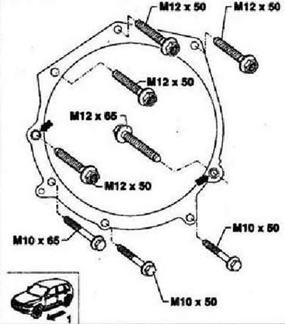
1 - Direction of movement. Drive plate to torque converter, 60 Nm, 6 pieces, install and remove using tool -V/175-. M12 bolts - M12, 80 Nm, M10 bolts - M10, 40 Nm, these bolts are located in the bottom flange. Two dowel sleeves in the engine -arrows-.
Visitor comments